This page details how to use the Andino X1 node. For a setup tutorial on Node Red for the Raspberry Pi and documentation on how to install custom nodes, please refer to Installing Node-Red on the Raspberry Pi

The Andino X1 node is a custom node that handles messages from the Andino X1 board and enables communication with the Arduino controller.
First, drag the node into the main panel in Node Red. When double clicking on the Andino X1 node, it can be set to one of three modes: Events, Relay 1 and Relay 2:
- Events: This mode allows to read the inputs of the AndinoX1. The node scans all messages it receives on its input side. If the message is coming from the Arduino controller, it outputs an object as msg.payload containing the current status of all inputs and counters:
- msg.payload.Counter1 (int): The number of pulses received by the Andino board through input 1
- msg.payload.Pin1 (int): The current value of the Pin1 input
- msg.payload.Counter2 (int): The number of pulses received by the Andino board through input 1
- msg.payload.Pin2 (int): The current value of the Pin2 input
- msg.payload.RelayStates1 (int): Shows 1 if the first relay is switched on, shows 0 if the first relay is switched off.
- msg.payload.RelayStates2 (int): Shows 1 if the second relay is switched on, shows 0 if the second relay is switched off.
- Note: The number of available Pin, RelayState and Counter Integers in the payload varies based on the board configuration and the selected Hardware version (HARD X) in the Andino X1 firmware.
- Relay 1: This mode is used to control Relay 1 of the Andino X1. It sends an output message switching the relay to on position if it receives either true or 1 as an input and to off position if it receives either false or 0.
- Relay 2: This mode is used to control Relay 2 of the Andino X1. It sends an output message switching the relay to on position if it receives either true or 1 as an input and to off position if it receives either false or 0.
- Relay 3: This mode is used to control Relay 3 of the Andino board. It sends an output message switching the relay to on position if it receives either true or 1 as an input and to off position if it receives either false or 0. Please note that not all hardware configurations have 3 relays. Using this setting on a configuration with two relays will not have any effect.
- Temperatures: This mode allows to read inputs from DS18B20 temperature sensors. This mode requires a "Hardware 4" Andino X1 board that has been set up according to this guide. The output of the node contains the following data:
- msg.payload.BusNr (int): The number of the bus that the following has been read from
- msg.payload.Temperature0 (float): The temperature from the sensor with the ID 0 on the bus.
- Note: The number of Temperature data floats differs according to the number of connected temperature sensors.
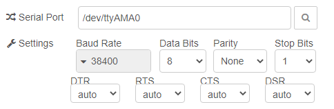
When in Events mode, the node's input must be connected to a Serial In node. When in Relay 1 / Relay 2 mode, the node's output must be connected to a Serial Out node.
In both cases, the serial node has to be configured to connect to /dev/ttyAMA0 with a Baud Rate of 38400.
The Andino X1 node can also be used with Andino IO boards, providing the same functionality. However, some prerequisites are necessary. For a detailed tutorial on all requirements, please refer to Andino IO Controller script
After having installed the script, the node can be set up in NodeRed. Instead of Serial In and Serial Out nodes, TCP In and TCP Out nodes have to be used. The rest of the configuration stays the same.
In the node properties, the TCP In node has to be set to Connect to port 1997 (by default). Enter localhost as the hostname. In the Output section, select stream of and String. All the other flields can be left blank.
The TCP Out node has to be set to Connect to port 1997 (by default). Enter localhost as the hostname. All the other flields can be left blank and the close connection after every message and decode Base64 message checkboxes should be unchecked.
For testing purposes, the AndinoX1 node can be wired up to inject nodes that are set to output a boolean value. The Andino X1 node is set to either Relay 1 or Relay 2 mode and conntected to a serial out node on its output side.
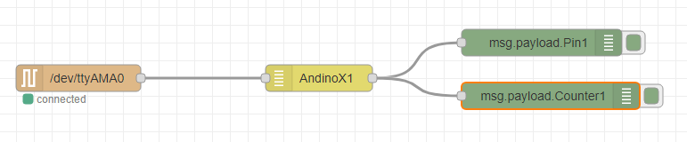
To read the values of the inputs of the andino boards, the node can be connected to a Serial In node on its input side. For testing purposes, this example connects two debug nodes on the output side that print the current value of the input (either 1 or 0) as well as the pulse number to the debug screen.
(Andino X1 version with 2G or 4G modem required)

In combination with the SMS processing nodes flows can be created to do specific tasks when receiving an SMS message. In this case, if the SMS content is on or off and switches the relay on or off respectively.
This example uses the reading SMS automatically example from the Andino SMS documentation but processes the message further instead of printing it to the debug screen.
After receiving the SMS content from the Process SMS node, we use a function node modify the message payload. This function node sends out true if the message payload is on and false if the message payload is off. The function node contains the following code:
if(msg.payload == "on"){
    msg.payload = true;
}else if(msg.payload == "off"){
    msg.payload = false;
}else{
    msg = null;
}
return msg;
The function node output is then processed by the AndinoX1 node as described in the Controlling the relays example.