This page provides a general introduction on the Andino X2. For more technical documentation on the base board, including setup tutorials and download links for drivers, please refer to Andino X2: Technical Documentation. For a setup tutorial on the Andino-X2 firmware, see Andino-X2: Firmware.
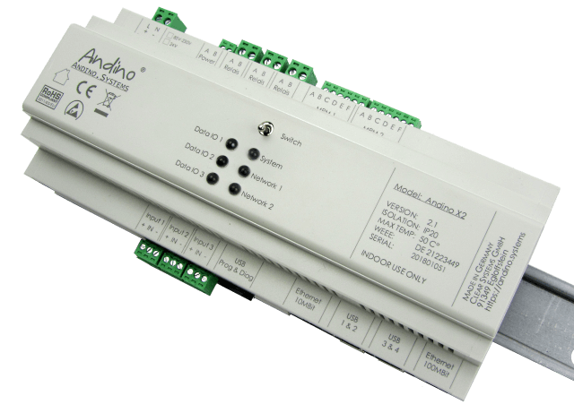
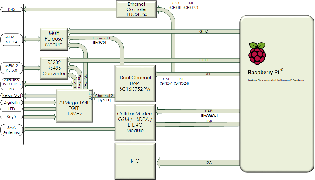
The Andino X2 is a microcontroller board for the Raspberry Pi in a DIN-rail housing for installation in a control cabinet. It is used to adapt digital inputs and outputs for a voltage of 24 V. The X2 has its own microcontroller for precise signal preprocessing and adaptation of signal generators and actuators. It also contains a Raspberry Pi 3. The inputs and outputs as well as the power supply of the Pi are optimally protected. Communication between the microcontroller and the Pi takes place via the UART interface.
The Andino X2 offers the following advantages:
The sensitive GPIO of the Raspberry Pi are protected. Fast signals can be precisely detected by the microcontroller. Actuators and sensors can be electrically connected to the Raspberry Pi. It provides an industrial power supply for the Raspberry Pi. Customized adapters from the Raspberry Pi GPIO or the micro controller IO can be connected electrically to terminals. Provides mounting on a DIN rail for installation in manifolds.

Andino X2 is a base board that allows the Raspberry Pi to be used in an industrial environment.
The X2 board has 85V to 230V AC Powersupply. Optional 9-24V wide-range DC input can be used. Powerful, reliable, stable power supply: 5 Volt, 2.6 Amp – enough power for the Raspberry, your USB hardware and customer-specific adaptation. The integrated EMC protection circuits protect the Pi from voltage surges and current surges on the supply line.
The 40-pin connector is compatible with Raspberry Pi 3
The Atmel, a Atmega 164P with 12 Mhz, microcontroller of the Andino X2 comes with an Arduino-compatible bootloader. The combination of Arduino and Raspberry Pi on the Andino X2 is ideally suited for use in home automation and sensor technology, as well as in more demanding industrial automation applications. The strengths of both boards complement each other perfectly. While the single-board computer Raspberry Pi can perform complex tasks (eg hosting of database and WebServer) as a full-value computer, the Arduino microcontroller can take care of the fast signal pre-processing. The Atmel Controller communicates via UART with the Pi. Programmable is the X1 with the Arduino IDE via USB from a PC or from a Raspberry (firmware update in the field).
Programmable 8-bit microcontroller (Atmega 164P 12Mhz) for adapting the inputs and outputs. Accurate and reliable detection of digital and analog signals.
The X2 board has three electrically isolated inputs (up to 5kV isolated) as well as three relay outputs for 230V volts and 4 amps. The IO is controlled by a microcontroller. Further GPIO of the Raspberry Pi as well as IO of the Microcontroller are led on an internal pin header. This makes it possible to bring own adaptations to the screw terminals.
Via the SPI and the I2C interface of the Raspberry Pi, further hardware extensions can be connected and led to the free screw terminals. Thus, a stable, control cabinet-compatible wiring is possible. Further Interfaces: RS485 / RS422 (2/4 lines), RS232, and CAN Bus will be available soon.
The integrated, battery-buffered RTC provides the correct time even if no NTP (time) server is available. The high-precision time chip DS3231 from Dallas Semiconductors is used. Due to the internal temperature compensation of the oscillator, the chip achieves a very high accuracy of ± 2ppm at 0 ° C to + 40 ° C.

- Data collection on production machines
- Collect and count Number of items, products
- Downtime detection
- Create Performance indicators Creation such as OEE, GAE and utilization
- Data collection at environmental monitoring stations
- Telecontrol and protocol converters
- Central in the house automation
- IoT nodes
- 2021 by Andino Systems
- Contact us by email