This page provides technical setup information for the Andino-UPS. For a general introduction on the product, please refer to Andino-UPS
For the firmware download, please visit our GitHub repository
The default firmware, witch is inital delivered uses 38400 Baud to communicate with the PC
This is what the Firmware do:
- Track the Powerdown Signal from the Power-Controller
- Read cyclical the Super-Cap voltage
- Controls the Power Fail Signal for the Client
- Controls the Power Down Relay to shut down / restart the Client
- Controlls the LEDs
- Communicate via the ttyX or COMx interface with a PC (or simular) see here how to connect
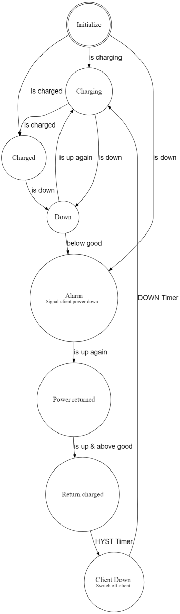
The Firmware is written as a Finite State Machine (FSM) It consits of states witch handles Events witch causes Actions and State transitions.
All commands or messages are sent and received via the UART
All character are ASCII.
Every command has to be terminated by CR or LF. Message ends with CR and LF.
| Command | Arguments | Action | Default | Example |
|---|---|---|---|---|
| RESET | none | Restart the Controller | - | RESET |
| INFO | none | Prints the current settings | - | INFO |
| HELP | none | Prints the current settings | - | INFO |
| TRCE | 0=no, 1=yes | Write Trace informations of the FSM to the UART | 0 | TRCE 1 |
| REGS | none | Dumps the internal registers in JSON format | - | REGS |
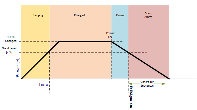
| GOOD | 20..98 | Sets the Power good level in % | 80 | GOOD 50 |
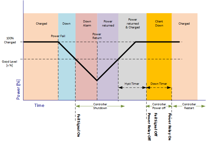
| HYST | 1..100 | Sets the Timer for the Shutdown of the Client | 5 | HYST 10 |
| DOWN | 1..100 | Sets the Timer for the Power off Client to Restart | 5 | DOWN 10 |
Send the Command REGS\r\n and the device will answer with a JSON Block
{
"chrg_sts": 0b0001010010100101,
"moni_sts": 0b0000001000000000,
"vc1": 2132,
"vc2": 2617,
"vc3": 2617,
"vc4": 2617,
"vin": 23848,
"vcap": 9985,
"vout": 23799,
"iin": 26,
"ichg": 0,
"temp": 25,
"index":0
}| Name | Description |
|---|---|
| chrg_sts | Charge Status Register |
| moni_sts | Monitor Status Register |
| vc1 | Voltage CAP1 |
| vc2 | Voltage CAP2 |
| vc3 | Voltage CAP3 |
| vc4 | Voltage CAP1 |
| vin | Input Voltage |
| vcap | Total CAP Voltage |
| vout | Output Voltage |
| iin | Input Current in mA |
| ichg | Charge Current in mA |
| temp | Core Temperature in C |
| index | upcounting message counter |
For more details please see here
If you enable the Trace "TRCE 1" this will be written: State / Event Value or State -> State transitions
Init / Enter  Val: 0
Init -> Charging
Init / Leave  Val: 0
Charging / Enter  Val: 0
Charging / Up  Val: 10
Charging / Level  Val: 6590
Charging / Level  Val: 6890
Charging / Level  Val: 7180
Charging / Level  Val: 7450
Charging / Level  Val: 7730
Charging / Level  Val: 7930
Charging / Level  Val: 8170
Charging / Level  Val: 8370
Charging / Level  Val: 8580
Charging / Level  Val: 8780
Charging / Level  Val: 9000
Charging / Level  Val: 9180
Charging / Level  Val: 9340
Charging / Level  Val: 9520
Charging -> Charged
Charging / Leave  Val: 0
Charged / Enter  Val: 0
Charged / Level  Val: 9680
Charged / Level  Val: 9870
Charged / Level  Val: 9990
Charged / Level  Val: 9980
Charged / Level  Val: 9990
Charged / Down  Val: 0
Charged -> Down
Charged / Leave  Val: 0
Down / Enter  Val: 0
Down / Level  Val: 9920
Down / Level  Val: 9860
Down / Level  Val: 9820
Down / Up  Val: 10
Down -> Charging
Down / Leave  Val: 0
Charging / Enter  Val: 0
Charging / Level  Val: 9920
Charging -> Charged
Charging / Leave  Val: 0
Charged / Enter  Val: 0
Charged / Level Val: 9990To develop or change the Firmware for the Andino UPS from a PC, please follow this steps:
- Download the Arduino IDE here
- Download the Firmware and save it in an Folder named UPS-V01
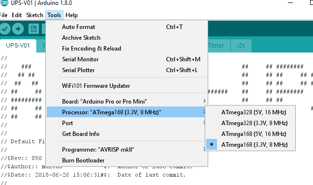
- Setup the Arduino IDE. (below)
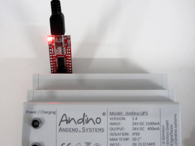
- Use the USB-TTL Uart adapter
The Andino UPS allows to program the Atmel Controller from the Raspberry Pi with avrdude or from a PC via a USB Adapter.
Insert the Adapter at the upper side of the Andino UPS (6-pin slot)
- 2020 by AndinoSystems
- Contact us by email