This page provides setup information for the Andino X1 Pico base board. For documentation on a specific Andino X1 Pico configuration and setup documentation for extensions, refer to the product-specific setup documentation.
The Raspberry Pi and the RP2040 communicate via the serial interface. To enable the serial interface in the Raspberry operating system, the following steps are necessary. These steps vary between the Bullseye and Bookworm operating systems. The internal serial interface apears as:
- Bookworm: /dev/ttyS0
- Bullseye: /dev/ttyAMA0
Start raspi-config

goto interface options

goto serial interface

Select the folowing to enable the serial interface as /dev/ttyS0


REBOOT
Install minicom
sudo apt-get install minicom
Start minicom
Setup minicom:

Save config as default:

For specific installations, for example if you want to use a custom firmware version for the Arduino microcontroller in combination with custom Raspberry Py hardware, it might be necessary to do a manual installation of the X1 software. To do so, follow this tutorial
First, edit boot/config.txt
sudo nano /boot/config.txtadd this at the end of the file..
enable_uart=1
dtoverlay=disable-bt
dtoverlay=miniuart-bt
Save and quit.
sudo nano /boot/cmdline.txtRemove “console=… (cut between ~~)
dwc_otg.lpm_enable=0 ~~console=serial0,115200 console=tty1~~ root=/dev/mmcblk0p2 rootfstype=ext4 .....Reboot the Raspberry Pi.
sudo rebootAs a testing tool, minicom is used. Install minicom, then enter setup:
sudo apt-get install minicom
sudo minicom --setup
Navigate Serial Port Setup, then Hardware Flow to No, set Device to /dev/ttyAMA0 or /dev/serial0, set BPS to 38400
+-----------------------------------------------------------------------+
| A - Serial Device : /dev/ttyAMA0                                      |
| B - Lockfile Location : /var/lock                                     |
| C - Callin Program :                                                  |
| D - Callout Program :                                                 |
| E - Bps/Par/Bits : 38400 8N1                                          |
| F - Hardware Flow Control : No                                        |
| G - Software Flow Control : No                                        |
|                                                                       |
| Change which setting?                                                 |
+-----------------------------------------------------------------------+
 | Screen and keyboard      |
 | Save setup as dfl        |
 | Save setup as..          |
 | Exit                     |
 | Exit from Minicom        |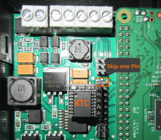
+--------------------------+The RTC usually comes pre-installed on the Andino board. However, if you have removed the RTC and want to re-install it, please note to skip the first pin. The RTC starts at PIN 2 (3.3 Volt). Otherwise the RTC will be destroyed.
For the software installation, we need to enable I2C and add the Module the RTC DS3231. To do so, first edit the /boot/config.txt:
sudo nano /boot/config.txtHere, uncomment dtparam=i2c_arm=on and add the dtoverlay=i2c-rtc,ds3231:
dtparam=i2c_arm=on
#dtparam=i2s=on
#dtparam=spi=on
dtoverlay=i2c-rtc,ds3231
Reboot the Pi. Then, edit the file /etc/modules and check if the line
i2c-devis present. If not, add it to the end of the file. Save and quit, then reboot once again.
I2C should now be enabled. Next, we need to install some more software, including some utilities for the RTC. To do so, execute the following commands:
sudo -s
chmod +x /etc/rc.local
apt-get install -y i2c-tools
apt-get purge -y fake-hwclock
apt-get remove fake-hwclock -y
dpkg --purge fake-hwclock
rm -f /etc/adjtime.
cp /usr/share/zoneinfo/Europe/Berlin /etc/localtime
ln -s /home/pi/bin/ntp2hwclock.sh /etc/cron.hourly/ntp2hwclock
sudo reboot now
Afterwards, reboot to test this RTC
i2cdetect -y 1

     0  1  2  3  4  5  6  7  8  9  a  b  c  d  e  f
00:          -- -- -- -- -- -- -- -- -- -- -- -- --
10: -- -- -- -- -- -- -- -- -- -- -- -- -- -- -- --
20: -- -- -- -- -- -- -- -- -- -- -- -- -- -- -- --
30: -- -- -- -- -- -- -- -- -- -- -- -- -- -- -- --
40: -- -- -- -- -- -- -- -- -- -- -- -- -- -- -- --
50: -- -- -- -- -- -- -- -- -- -- -- -- -- -- -- --
60: -- -- -- -- -- -- -- -- 68 -- -- -- -- -- -- --
70: -- -- -- -- -- -- -- --
pi@raspberrypi:~ $

hwchwclock -w
hwclock -r
The RTC software is now installed and ready for use.
Optional: This Python script sets the NTP Time to the HWClock as long a NTP connection can established. Place this script at /home/pi/bin/ntp2hwclock.sh (for example, see above)
#!/bin/bash
# Location of logfile
LOGFILE="/usr/local/oeebox/etc/log/ntp.log"
if [ ! -f $LOGFILE ]; then
  touch $LOGFILE
fi
# Set the maximum allowed difference in seconds between Hw-Clock and Sys-Clock
maxDiffSec="2"
msgNoConnection="No connection to time-server"
msgConnection="Connection to time-server"
# Check for NTP connection
if ( ntpq -p | grep -q "^*"  ); then
        echo $msgConnection >> $LOGFILE
        echo "---------------------------------"  >> $LOGFILE
        secHwClock=$(sudo hwclock --debug | grep "^Hw clock time" | awk '{print $(NF-3)}')
        echo "HwClock: $secHwClock sec" >> $LOGFILE
        secSysClock=$(date +"%s")
        echo "SysClock: $secSysClock sec" >> $LOGFILE
        echo "---------------------------------" >> $LOGFILE
        secDiff=$(($secHwClock-$secSysClock))
        # Compute absolute value
        if ( echo $secDiff | grep -q "-" ); then
            secDiff=$(echo $secDiff | cut -d "-" -f 2)
        fi
        echo "Difference: $secDiff sec" >> $LOGFILE
        msgDiff="HwClock difference: $secDiff sec"
        if [ "$secDiff" -gt "$maxDiffSec" ] ; then
                echo "---------------------------------" >> $LOGFILE
                echo "The difference between Hw- and Sys-Clock is more than $maxDiffSec sec." >> $LOGFILE
                echo "Hw-Clock will be updated" >> $LOGFILE
                # Update hwclock from system clock
                sudo hwclock -w
                msgDiff="$msgDiff --> HW-Clock updated." >> $LOGFILE
        fi
        if !(awk '/./{line=$0} END{print line}' $LOGFILE | grep -q "$msgConnection") || [ "$secDiff" -gt "$maxDiffSec" ]; then
                echo $(date)": "$msgConnection". "$msgDiff >> $LOGFILE
        fi
else
        # No NTP connection
        echo $msgNoConnection
        if !(awk '/./{line=$0} END{print line}' $LOGFILE | grep -q "$msgNoConnection"); then
                echo $(date)": $msgNoConnection" >> $LOGFILE
        fi
fi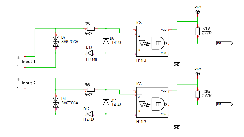
#define IN_1       7 // PD7
#define IN_1_PORT  PIND
#define IN_1_PIN   7

#define IN_2       6 // PD6
#define IN_2_PORT  PIND
#define IN_2_PIN   6

#define OUT_1     14 // PC0 analog 0
#define OUT_2     15 // PC1 analog 1

void setup()
{
    pinMode(IN_1,INPUT);
    digitalWrite(IN_1, HIGH); // activate pull up resistor
    pinMode(IN_2,INPUT);
    digitalWrite(IN_2, HIGH); // activate pull up resistor
    pinMode(OUT_1,OUTPUT);
    pinMode(OUT_2,OUTPUT);
}

    digitalWrite(OUT_1, 1);
    digitalWrite(OUT_1, 0);
    digitalWrite(OUT_2, 1);
    digitalWrite(OUT_2, 0);
if( bitRead( IN_1_PORT, IN_1_PIN ) )The Andino X1 already comes with a firmware for the microcontroller pre-installed. However, if you want to update the board firmware or program a custom firmware, this can be done using the Arduino IDE.
First, download and install the Arduino IDE for your platform. Install the software, then USB Mini-B cable to connect the Andino X1 to your PC before opening it.
Detailed instructions for the preparation of the Arduino IDE can be found here
The default Andino X1 Pico firmware can count impulses from the digital inputs, display the input states, switch or pulse relays and read temperature data from DS18B20 temperature sensors. Count stops are cyclically sent to the Raspberry. The digital inputs are additionally de-bounced.
This firmware and its correct configuration is also a prerequisite for using the Andino X1 Node-Red node to integrate digital inputs, temperature data and relay control into Node-Red flows.
More information on the firmware can be found at: Standard Andino X1 Firmware.
The default UART Settings for the firmware are 38400 / 8 / n / 1
Programming your own firmware for the Andino X1 Pico is roughly equivalent to programming firmware for an Arduino board. The following steps have to be followed:
- Install the Aruino IDE on your PC.
- Set the Arduino IDE to the correct board, voltage and frequency
- Set the Jumper of the Andino to the USB configuration (see image below)
- Program the Firmware and test it
- Set the Jumper back to the Raspberry Pi mode
