A video tutorial on the setup and usage of the 2G modem is available here:

For a text-based explanation see below!
Important: Before installation, remove the pin code from the SIM card (e.g. using a Smartphone)!
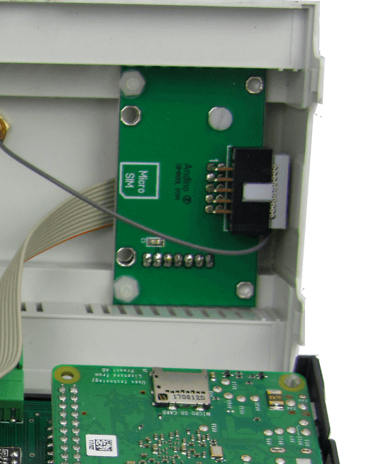
Open the Housing and insert the Micro SIM.
The Modem is connected to the internal UART of the Raspberry Pi.
The Reset Line of the Modem is connected to GPIO 17.
For downloads see our GitHub repository.
init.sh     initialize the Ports to reset Modem
stop.sh     Stop (hold in reset) the Modem
start.sh    Start the Modem (release reset)
restart.sh  Stop and Start again

dial.sh     Init the DialIn
hangup.sh   Shutdown PPP

log.sh Tail the logFirst, run
sudo nano /boot/cmdline.txtTo ensure correct shell behavior, remove entries beginning with console= in this file. An example for entries needing to be removed is highlighted here with >>[entry]<<. After having edited the file, save with Ctrl+O and exit with Ctrl+X.
dwc_otg.lpm_enable=0 >>console=serial0,115200 console=tty1<< root=/dev/mmcblk0Afterwards, run
sudo nano /boot/config.txtJump to the end of the file and add
enable_uart=1
dtoverlay=disable-bt
dtoverlay=miniuart-bt
Finish by rebooting the pi
sudo reboot nowFirst, install some tools for testing
sudo apt-get install screen elinks minicomTesting the modem connection can be done via minicom. For the initial setup, run
sudo minicom --setupAfter having completed the initial setup, minicom can be run without the --setup flag in the future. Enter Serial port setup
+-----[configuration]------+
| Filenames and paths      |
| File transfer protocols  |
| Serial port setup        |
| Modem and dialing        |
| Screen and keyboard      |
| Save setup as dfl        |
| Save setup as..          |
| Exit                     |
| Exit from Minicom        |
+--------------------------+
Here the modem connection can be set up. On the Andino X1, to connect to the 2G modem, the serial device has to be set to /dev/ttySC1. On the Andino IO, set the serial device to /dev/ttyAMA0. Also make sure that Hardware Flow Control is set to No.
+-----------------------------------+
| A -Serial Device  : /dev/ttySC1   |
| B - Lockfile Location : /var/lock |
| C -   Callin Program  :           |
| D -  Callout Program  :           |
| E -Bps/Par/Bits   : 38400 8N1     |
| F - Hardware Flow Control : No    |
| G - Software Flow Control : No    |
|                                   |
|Change which setting?              |
+-----------------------------------+
After completing the configuration, press the Esc key to return to the main setup menu, choose Save setup as dfl to save the configuration for future usage and exit.
To check the connection to the modem, first run at. Running ati will show the version of the modem.
at
OK
ati
SIM800 R14.18
OK
For debugging purposes, Errors can be set to be shown as text. This can be accomplished by running at+cmee=2.
# Show Error as text
AT+CMEE=2
The network connectivity can also be tested, making sure that the SIM works correctly and the modem has good reception.
# SIM Ready?
AT+CPIN?
+CPIN: READY
# Network available?
AT+COPS?
+COPS: 0,0,"D1"
# Signal strength?
AT+CSQ
+CSQ: 4,0
The values for the signal strength can be interpreted as follows:

After having confirmed that the modem has established a connection, minicom can be closed by pressing Ctrl+a, followed by the x key. The modem can be used for sending and receiving messages or connecting to the internet using ppp. For the next steps refer to the links below.