The Andino XIO is an industrial PC based on the Raspberry Pi. It provides 6 digital inputs and 6 relay outputs that are connected to rigid connectors. This, combined with its sturdy housing and DIN-Rail mount makes the device ideal for operation in industrial environments.


The Andino XIO contains a Raspberry Pi 3B+ / Raspberry Pi 4, depending on the configuration. The Raspberry Pi is connected to the XIO via its GPIO. The usage of a Raspberry Pi allows for relatively resource intensive tasks to be run on the XIO without problems. It also allows for the use of a wide array of software, both custom-developed by Andino Systems, as well as the wider Raspberry Pi OS and Linux community.
The main feature of the Andino XIO is its connectivity. It provides the following options:
- 6x relays (240VAC, 16 A)
- 6x isolated digital inputs
The relays and inputs can easily be controlled via Node-Red as described in this tutorial. If you want to read inputs and control relays via Python, please refer to our Guide using inputs and relays using the RPi.GPIO library.
Relays and Inputs are simply connected to the Raspberry Pi GPIO pins. For more documentation on this see section Wiring of the inputs
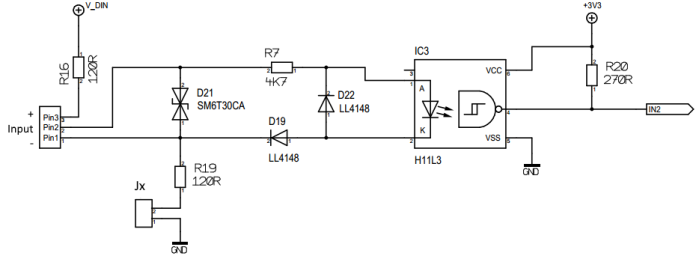
The isolated digital inputs can be run in two modes:
- Isolate (active) mode: Voltage must be provided
- Partial-Isolate (passive) mode: Switch can directly be connected
Furthermore, the Raspberry Pi inside the Andino XIO provides the following IO:
- For Raspberry Pi 3B+: 2x USB 2.0, 1x Ethernet (100Mbit/s)
- For Raspberry Pi 4: 2x USB 3.0, 2x USB 2.0, Gigabit Ethernet
A 1.3 inch, 128 x 64 pixel I2C OLED display enables easy monitoring of data from the IO.
Installation instructions and usage in Node Red are here

The inputs and relays are wired to the following GPIO pins of the Raspberry Pi:
- Inputs: GPIO6, GPIO13, GPIO19, GPIO26, GPIO21, GPIO20
- Relays: GPIO24, GPIO25, GPIO8, GPIO7, GPIO12, GPIO16
The Inputs are calculated for 24 Volt Input. Normally a signal of 24 Volt is applied to Pin 2 and the Ground to Pin 1. (active Mode)
By closing the Jumper X the Inputs can be driven in passive Mode or Dry Contact. This means a Switch / Relay contact can be connected between Pin 3 and Pin 2.

- The inputs and outputs can easily be controlled/read from using Node-Red.
- If you want to read inputs and control relays via Python, please refer to our Guide using inputs and relays using the RPi.GPIO library.
- The Andino XIO setup can be done by running our Andinopy Setup script. This will automatically install all necessary software, set the correct values to configuration files and set up Andinopy TCP for easy control of all board IO via TCP or Node-Red.
- 2022 by AndinoSystems
- Contact us by email