For setup documentation, please refer to the section at the bottom!
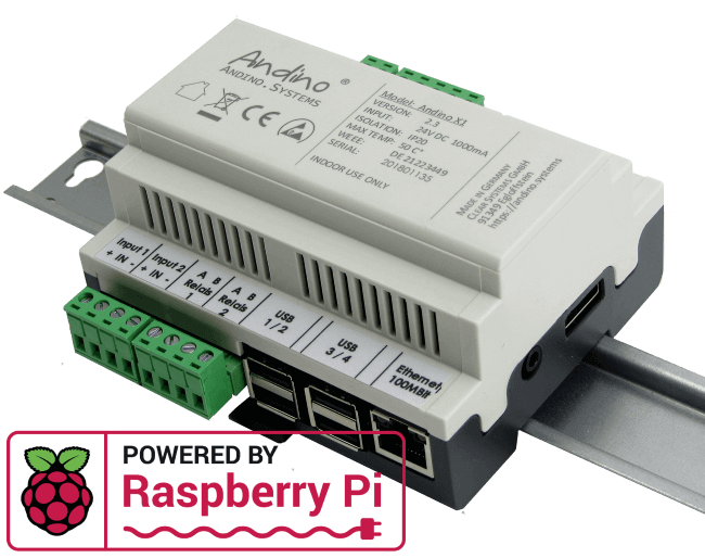
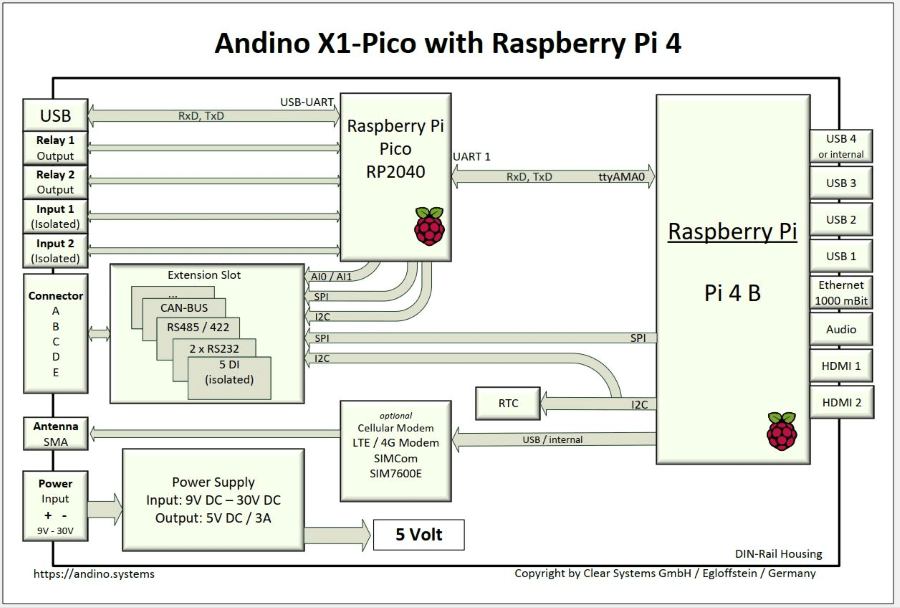
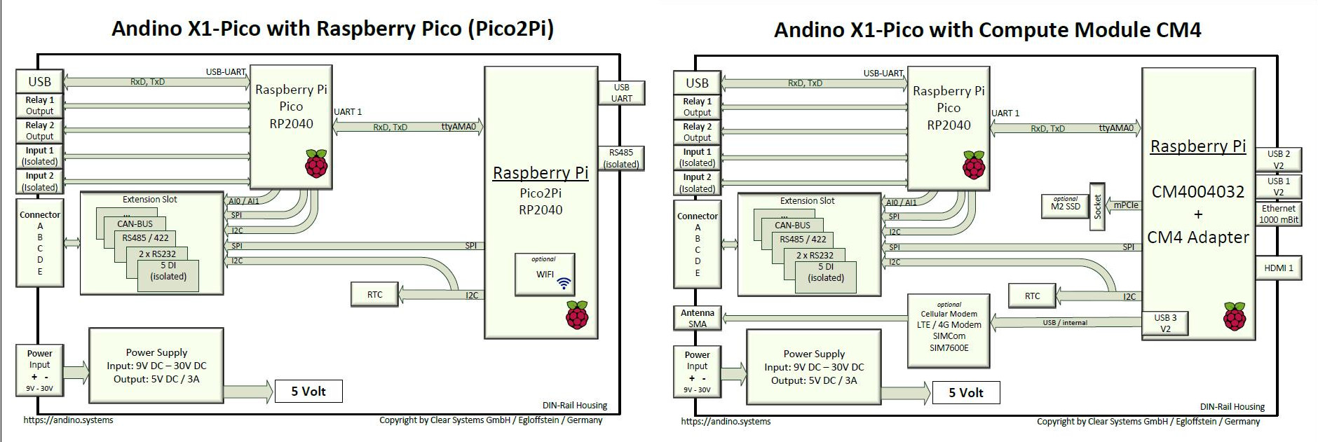
The Andino X1 Pico is a microcontroller board for the Raspberry Pi in a DIN-rail housing for installation in a control cabinet in industrial environments. Its built-in Arduino compatible microcontroller is used to adapt digital inputs and outputs for a voltage of 24 V, with the controller ensuring precise signal preprocessing and adaptation of signal generators and actuators. It also contains a Raspberry Pi 4 or 3B+, depending on the configuration. The protection of the inputs and outputs through ridgid connectors, as well as the robust power supply for the Pi and board enable usage in an industrial environment. Communication between the microcontroller and the Pi takes place via the UART interface.


[Andinopy]() is a custom made open source software solution for all Andino boards that allows for easy communication with the board IO in one centralized place. It also provides a TCP server that allows for its usage in conjunction with other software like Node-Red.
If you do not choose to order the Andino X1 with a pre-installed SD card, all necessary prerequisites, Node-Red and Andinopy can easily be installed via our install script. If you want to deploy multiple Andino X1's with the same software installation, this can easily be achieved by cloning one SD card via rpi-clone.
The 40-pin connector is compatible with Raspberry Pi 3B+ and Raspberry Pi 4. This enables easy data processing using our custom software, python libraries and node-red nodes that are purpose-built for a variety of usage scenarios. Since all of our software is based on Raspberry Pi OS, you can also choose from a large collection of software built for the Raspberry Pi and Debian.
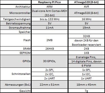
The core of the X1 has been reworked. Instead of an ATmega 328p, the RP2040 from Raspberry is now used. The RP2040 performs the same tasks as the ATmega 328p before, only better, faster and with more computing power.


In addition, a connection to the Pico via USB is now possible, which results in the advantage that a total of 3 additional expansion boards (X1) can be connected. Thus a multiplicity of sensors and/or actuators can be controlled. In comparison of the two variants, the sampling rate of the sensor data was again significantly increased. Real-time pre-processing is thus achieved.
The X1 board has a 9-24V wide-range DC input with reverse polarity protection. Powerful, reliable, stable power supply: 5 Volt, 2.6 Amp (3.5 A by the X1- Pico) – enough power for the Raspberry, your USB hardware and customer-specific adaptation. The integrated EMC protection circuits protect the Pi from voltage surges and current surges on the supply line. For especially mission-critical projects, the Andino UPS can be used to allow for a shutdown period on sudden power loss, thus preventing data corruption.
The X1 board has two electrically isolated inputs (up to 5kV isolated) as well as two relay outputs for 42 volts and 1 amp. The rest of the Raspberry Pi GPIO Pins as well as IO of the Microcontroller are led on an internal pin header. This makes it possible to bring own adaptations to the screw terminals.
Via the SPI and the I2C interface of the Raspberry Pi, further hardware extensions can be connected and led to the free screw terminals. These extensions are usually sold as one product with the X1 board and a Raspberry Pi. For an overview of all the available versions, please refer to the shop page of the Andino X1.

The integrated, battery-buffered RTC provides the correct time even if no NTP (time) server is available. The high-precision time chip DS3231 from Dallas Semiconductors is used. Due to the internal temperature compensation of the oscillator, the chip achieves a very high accuracy of ± 2ppm at 0 ° C to + 40 ° C.
- Data collection on production machines
- Collect and count Number of items, products
- Downtime detection
- Create Performance indicators Creation such as OEE, GAE and utilization
- Data collection at environmental monitoring stations
- Telecontrol and protocol converters
- Central in the house automation
- IoT nodes
First, install python:
sudo apt-get install python python-pipInstall pyserial:
pip install pyserialCreate file 'readAMA0.py'
python
import serial
ser=serial.Serial('/dev/ttyAMA0', 38400, timeout=30)
line=ser.readline()
print line
python readAMA0.pyFor setup documentation, please select your product variant from the list below:
- Andino X1 with Raspberry Pi, Breadboard, Heatsink and RTC
- Andino X1 with Raspberry Pi, isolated RS485/RS422, Heatsink and RTC
- Andino X1 with Raspberry Pi, dual Channel RS232, Heatsink and RTC
- Andino X1 with Raspberry Pi, 7 digital Inputs, Heatsink and RTC
- Andino X1 with Raspberry Pi, 2DO/1DI, Heatsink and RTC
- Andino X1 with Raspberry Pi, CAN Bus, Heatsink and RTC
- Andino X1 with Raspberry Pi, LoraWAN, Heatsink and RTC
- Andino X1 with Raspberry Pi, 4G Modem, Heatsink and RTC
For more technical documentation on the base x1 board without any extensions, including setup tutorials and download links for drivers and firmware, please refer to Andino X1: BaseBoard Setup.
- 2021 by AndinoSystems
- Contact us by email