This page provides documentation on how to control relays from Node-Red and read data from the digital inputs of Andino Boards. This is supported on all boards, except the Andino X1 and Andino X2. The relays and inputs on the Andino X1 can be controlled via the X1 Node-Red Node instead.
To control Relays and Read Inputs from within Node-Red, you first need to install Node-Red on your Raspberry Pi. By following our tutorial on doing so, the necessary Raspberry Pi Nodes will be installed automatically as well.
Depending on your device, different pins of the Raspberry Pi are mapped to different relays and inputs. Since the usage of the wrong GPIO in Node-Red can, at worst, cause hardware damage, it is important to use the correct GPIO for your device. These are:
Andino IO:
- Inputs: GPIO13, GPIO19, GPIO 16, GPIO 26, GPIO20, GPIO21
- Outputs: GPIO5, GPIO6, GPIO12
Andino XIO:
- Inputs: GPIO6, GPIO13, GPIO19, GPIO26, GPIO21, GPIO20
- Outputs: GPIO24, GPIO25, GPIO8, GPIO7, GPIO12, GPIO16
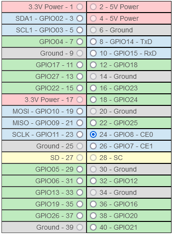
Make sure, that when selecting the pin in the node properties, you always select the pins with the corresponding GPIO number, not the pin number.

In this example, Pin 24 is selected, which corresponds to GPIO8. In this tutorial and most places on this website, GPIO numbers are used unless explicitly stated otherwise.
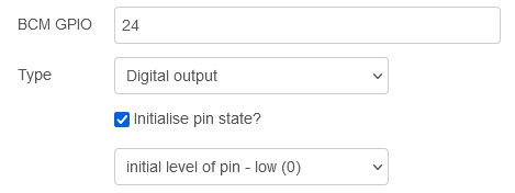
Relays of the Andino boards can be controlled using the rpi gpio out node. It can be assigned to one specific relay that can then be switched on or off by entering the integer 1 or 0 as the payload on the input of the node. Within the properties of the node (double click), set the GPIO number and choose digital input as the type. The pin state can also be initialized. This makes sure that the relay is always set to either on or off when the Pi is booted.

Inputs can be read using the rpi gpio in node. It can be assigned to one specific input and will automatically output a message with either 1 or 0 as its payload, whenever the state of the input changes. Within the properties of the node (double click), set the GPIO number. If needed for the connected device, a resistor can also be configured. You can also change the debounce of the input.

If you want to control the inputs and relays on an Andino XIO from another device via TCP, you can use Node-Red to implement a similar functionality as is available via the Andino IO Controller script for the Andino IO. This can be achieved using a TCP in node that receives Strings and then passes it on for further processing via switch and function nodes. An example for this is included in example flow available for download below.
The following flows providing examples on how to use Node-Red to control relays and read inputs are available:
The flows can be imported through the Import menu (click on Hamburger button in the top right corner in the Node-Red interface). There, either upload the file or paste the file contents in the field below.
- 2022 by AndinoSystems
- Contact us by email