This page provides setup information for the Andino X1 base board. For documentation on a specific Andino X1 configuration and setup documentation for extensions, refer to the product-specific setup documentation.
Important: It is now possible to set up all Andino boards using our Andinopy setup script.
This will automatically configure hardware settings, download necessary overlays and optionally also installs the Andinopy library / TCP stack and Node-Red. You will not need to follow this baseboard setup documentation when using the setup script.
Not all connectivity of the Andino IO can be installed via the scripts and used via Andinopy, however. Because of this, there is some more documentation about the rest of the IO on this page:
- RS232 / RS485
- CAN
- DS1820 Temperature sensor
- 2G Modem: Sending SMS / Internet connectivity
- 4G Modem: Internet connectivity
- Using Modbus RTU / Modbus TCP
A manual installation of the Andino IO can be necessary or useful if you want to have a very specific software setup and don't intend on using Andinopy. In this case, follow the following documentation:
The recommended way to enable SPI is downloading the pre-compiled overlay from GitHub. To do so, we first need to download the overlay from GitHub to our home directory:
cd ~/
wget https://github.com/andino-systems/Andino/raw/master/Andino-IO/BaseBoard/sc16is752-spi0-ce1.dtbo
Now, copy the downloaded file to /boot/overlays/:
sudo cp sc16is752-spi0-ce1.dtbo /boot/overlays/If you would rather like to compile the overlay yourself, the sources can be found on our GitHub too. First, download the sources, as well as the make-file into your home directory
cd ~/
wget https://github.com/andino-systems/Andino/raw/master/Andino-IO/BaseBoard/sc16is752-spi0-ce1.dts
wget https://github.com/andino-systems/Andino/raw/master/Andino-IO/BaseBoard/makedts.sh
Make the make-file executable and run it. This will compile the source code and move the compiled file to /boot/overlays.
chmod +x ./makedts.sh
sudo ./makedts.sAfter having installed the overlay, stop getty on serial0. Edit /boot/cmdline.txt:
sudo nano /boot/cmdline.txt Here, remove all intries starting with console=… (see example below, all bold entries have to be removed).
dwc_otg.lpm_enable=0 console=serial0,115200 console=tty1 root=/dev/mmcblk0p2 rootfstype=ext4 .....
Save and quit the file. Afterwards, some changes in the /boot/config.txt have to be made:
sudo nano /boot/config.txtJump to the end of the file and add the following lines:
# -----------------------
# Andino IO from here
# -----------------------

# SPI on
dtparam=spi=on

# I2C on
dtparam=i2c_arm=on

# RTC
# sudo apt-get install -y i2c-tools
# i2cdetect -y 1
dtoverlay=i2c-rtc,ds3231

# CAN on SPI 0.0
# sudo apt-get install can-utils
# sudo ip link set can0 up type can bitrate 125000
# sudo ifconfig
# cansend can0 456#43414e2054657374
# candump can0
dtoverlay=mcp2515-can0,oscillator=16000000,interrupt=25

# 1. UART
# /dev/ttyAMA0 = Modem
enable_uart=1
dtoverlay=pi3-disable-bt-overlay
dtoverlay=pi3-miniuart-bt

# 2. SPI-UART on SPI 0.1
# /dev/ttySC0 = RS485
# /dev/ttySC1 = RS232
dtoverlay=sc16is752-spi0-ce1,int_pin=24,xtal=11059200

# DS1820 Temp sensor
# cat   /sys/bus/w1/devices/28-00000a990ab5/w1_slave
dtoverlay=w1-gpio-pullup,gpiopin=22,extpullup=on
dtoverlay=w1-gpio,gpiopin=22
Save and quit, then reboot the Pi.
sudo reboot nowFinally, edit the file /etc/modules and check if the line
i2c-devis present. If not, add it to the end of the file. Then save and quit.
The UART SPI driver should now be fully configured and the two devices /dev/ttySC0 and /dev/ttySC1 should be visible.
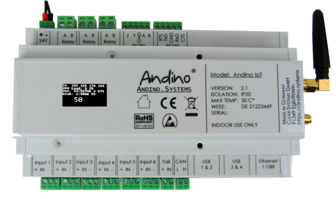
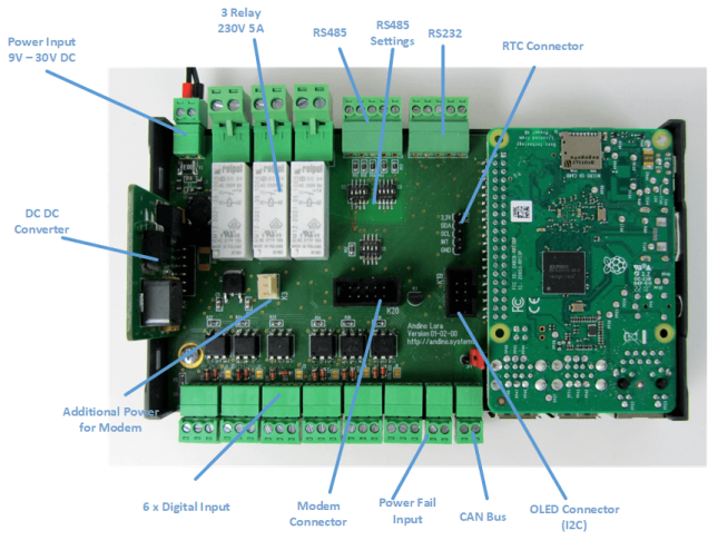
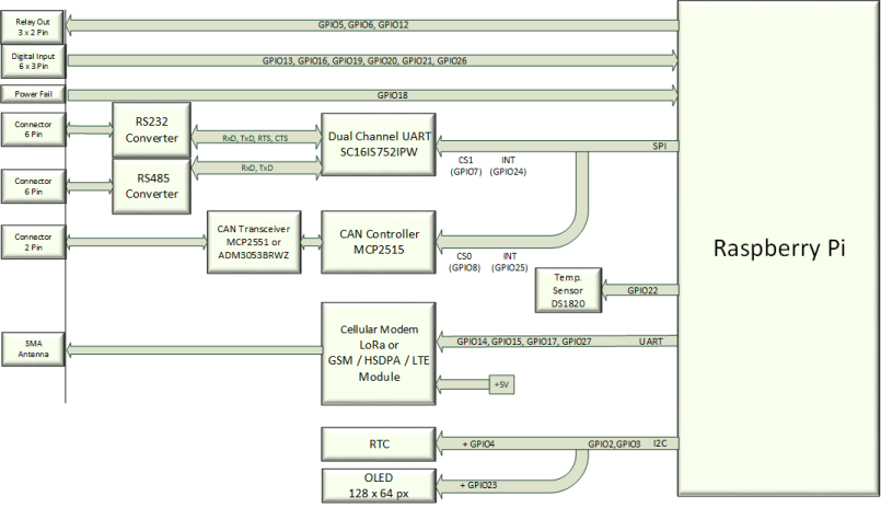
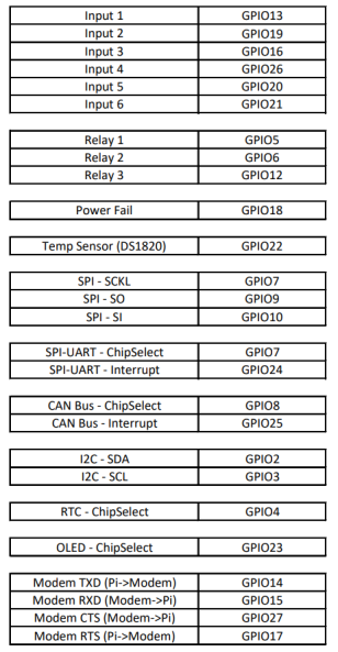
The digital inputs are connected to the GPIO:
- Input1: GPIO13
- Input2: GPIO19
- Input3: GPIO16
- Input4: GPIO26
- Input5: GPIO20
- Input6: GPIO21
The Inputs are calculated for 24 Volt Input. Normaly a signal of 24 Volt is applied to Pin 2 and the Ground to Pin 1. (active Mode)
By closing the JumperX the Inputs can be driven in passive Mode or Dry Contact. This means a Switch / Relaycontact can be conneted between Pin 3 and Pin 2.


The Relay are controlled by the GPIO:
- Relay1: GPIO5
- Relay2: GPIO6
-
Relay3: GPI12
# Export
sudo echo "5" > /sys/class/gpio/export
sudo echo "6" > /sys/class/gpio/export
sudo echo "12" > /sys/class/gpio/export
# Set to output
sudo echo "out" > /sys/class/gpio/gpio5/direction
sudo echo "out" > /sys/class/gpio/gpio6/direction
sudo echo "out" > /sys/class/gpio/gpio12/direction
# Switch on
echo "1" > /sys/class/gpio/gpio5/value
echo "1" > /sys/class/gpio/gpio6/value
echo "1" > /sys/class/gpio/gpio12/value
The Relays can drive 230V and up to 5 ampere. There a no Fuses at the relay contacts!!
The Power Fail Input can be used to inform the Raspberry about a Mains Power loss. This can be done by a Switch- / Relay-Contact. Just bridge Pin1 and Pin2 to signal Power good/fail.
- Fail Input: GPI18
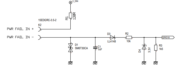
This feature can be used together with the Andino UPS
sudo echo "18" > /sys/class/gpio/export
sudo echo "in" > /sys/class/gpio/gpio18/direction
cat /sys/class/gpio/gpio18/valueThe OLED Display is connected via the I2C Bus with the address 68. This can be seen when checking the i2c devices:
apt-get install -y i2c-tools
i2cdetect -y 1

     0  1  2  3  4  5  6  7  8  9  a  b  c  d  e  f
00:          -- -- -- -- -- -- -- -- -- -- -- -- --
10: -- -- -- -- -- -- -- -- -- -- -- -- -- -- -- --
20: -- -- -- -- -- -- -- -- -- -- -- -- -- -- -- --
30: -- -- -- -- -- -- -- -- -- -- -- -- 3c -- -- --
40: -- -- -- -- -- -- -- -- -- -- -- -- -- -- -- --
50: -- -- -- -- -- -- -- -- -- -- -- -- -- -- -- --
60: -- -- -- -- -- -- -- -- UU -- -- -- -- -- -- --
70: -- -- -- -- -- -- -- --
0x3C is the OLED-Display 0x68 is the RTC
To print custom text on the display through external programs (e.g. Node-Red), you need to install Andinopy TCP. To do so, follow this installation instruction.
Execute this
sudo -s
chmod +x /etc/rc.local
apt-get purge -y fake-hwclock
apt-get remove fake-hwclock -y
dpkg --purge fake-hwclock
rm -f /etc/adjtime.
cp /usr/share/zoneinfo/Europe/Berlin /etc/localtime
ln -s /home/pi/bin/ntp2hwclock.sh /etc/cron.hourly/ntp2hwclock
sudo reboot now

hwclock -w
hwclock -r
This Python script sets the NTP Time to the HWClock as long a NTP connection can established. Place this script at /home/pi/bin/ntp2hwclock.sh (for example, see above)
#!/bin/bash
# Location of logfile
LOGFILE="/usr/local/oeebox/etc/log/ntp.log"
if [ ! -f $LOGFILE ]; then
  touch $LOGFILE
fi
# Set the maximum allowed difference in seconds between Hw-Clock and Sys-Clock
maxDiffSec="2"
msgNoConnection="No connection to time-server"
msgConnection="Connection to time-server"
# Check for NTP connection
if ( ntpq -p | grep -q "^*"  ); then
        echo $msgConnection >> $LOGFILE
        echo "---------------------------------"  >> $LOGFILE
        secHwClock=$(sudo hwclock --debug | grep "^Hw clock time" | awk '{print $(NF-3)}')
        echo "HwClock: $secHwClock sec" >> $LOGFILE
        secSysClock=$(date +"%s")
        echo "SysClock: $secSysClock sec" >> $LOGFILE
        echo "---------------------------------" >> $LOGFILE
        secDiff=$(($secHwClock-$secSysClock))
        # Compute absolute value
        if ( echo $secDiff | grep -q "-" ); then
            secDiff=$(echo $secDiff | cut -d "-" -f 2)
        fi
        echo "Difference: $secDiff sec" >> $LOGFILE
        msgDiff="HwClock difference: $secDiff sec"
        if [ "$secDiff" -gt "$maxDiffSec" ] ; then
                echo "---------------------------------" >> $LOGFILE
                echo "The difference between Hw- and Sys-Clock is more than $maxDiffSec sec." >> $LOGFILE
                echo "Hw-Clock will be updated" >> $LOGFILE
                # Update hwclock from system clock
                sudo hwclock -w
                msgDiff="$msgDiff --> HW-Clock updated." >> $LOGFILE
        fi
        if !(awk '/./{line=$0} END{print line}' $LOGFILE | grep -q "$msgConnection") || [ "$secDiff" -gt "$maxDiffSec" ]; then
                echo $(date)": "$msgConnection". "$msgDiff >> $LOGFILE
        fi
else
        # No NTP connection
        echo $msgNoConnection
        if !(awk '/./{line=$0} END{print line}' $LOGFILE | grep -q "$msgNoConnection"); then
                echo $(date)": $msgNoConnection" >> $LOGFILE
        fi
fiThe RS232 and RS485 based on the SPI Uart from NXP SC16IS752.
Important: For RS232, make sure that the ground pin (GND) has the same potential as the minus pin of the power input! Furthermore, the RS232 bus is not galvanically insulated!
After prepare the Debian for the use of the SPI Uart (see Prepare Debian) the /dev/ttySC1 is the RS232 Channel. The Signals on the RS232 Port are +-12 Volt.
You can exit minicom with CTRL-A then X
sudo apt-get install minicom
sudo nano minicom –setup
# press Serial Port Setup

+-----------------------------------------------------------------------+
| A -    Serial Device      : /dev/ttySC1                               |
| B - Lockfile Location     : /var/lock                                 |
| C -   Callin Program      :                                           |
| D -  Callout Program      :                                           |
| E -    Bps/Par/Bits       : 38400 8N1                                 |
| F - Hardware Flow Control : No                                        |
| G - Software Flow Control : No                                        |
|                                                                       |
|    Change which setting?                                              |
+-----------------------------------------------------------------------+
        | Screen and keyboard      |
        | Save setup as dfl        |
        | Save setup as..          |
        | Exit                     |
        | Exit from Minicom        |
+--------------------------+sudo apt-get install python-serialafter that you can send data:
import serial
import time

ser = serial.Serial(
               port="/dev/ttySC1",
               baudrate = 9600,
               parity=serial.PARITY_NONE,
               stopbits=serial.STOPBITS_ONE,
               bytesize=serial.EIGHTBITS,
               timeout=3
           )

for i in range(2):
        ser.setRTS(False)
        time.sleep(0.01)
        ser.write(str(i)+ b"Hello 232\n")
        time.sleep(0.1)
        s = ser.readline()
        print( s.rstrip() )
        ser.setRTS(True)
ser.close()After prepare the Debian for the use of the SPI Uart (see Prepare Debian) the /dev/ttySC0 is the RS485 Channel. It can be used as full duplex RS422 or as two wire RS485. In RS485 Mode the transmitter can be switched on either by the RTS signal or automaticaly.
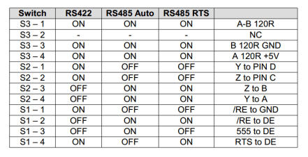
Send in manual mode
for i in range(2):
        # Transmitter on
        ser.setRTS(False)
        time.sleep(0.01)
        ser.write(str(i)+ b"Hello 485\r\n")
        time.sleep(0.1)
        s = ser.readline()
        print( s.rstrip() )
        # Transmitter off
        ser.setRTS(True)
Send in RS485 Auto mode
for i in range(2):
        ser.write(str(i)+ b"Hello 485\r\n")
        time.sleep(0.1)
        s = ser.readline()
print( s.rstrip() )The CAN Bus based on the Microchip MCP2515 and the Tranceiver MCP2551. It is supported by the Raspberry Pi.
sudo apt-get install can-utils
sudo ip link set can0 up type can bitrate 125000
sudo ifconfig can0
cansend can0 456#43414e2054657374
# or
candump can0The Device has a Build in temperatur Sensor DS1820. The Sensor is wired to GPIO 22.
ls /sys/bus/w1/devices/
cat   /sys/bus/w1/devices/28-00000a990ab5/w1_slave
6a 01 4b 46 7f ff 06 10 5f : crc=5f YES
6a 01 4b 46 7f ff 06 10 5f t=22625
This is 22.6225 Degrees Celsius
For the 2G modem (not present in all Andino IO configurations), please refer to our documentation for:
For the 4G modem (not present in all Andino IO configurations), please refer to our documentation for:
The LoRa WAN modem (not present in all Andino IO configurations) allows the Raspberry Pi to communicate with an existing LoRa WAN network and is connected via the internal RS232 connector. Please refer to the LoRa WAN Modem (RN2483) Setup Documentation
Modbus RTU can be used via RS485. Modbus TCP is also supported on the Raspberry Pi via Pymodbus. To install PyModbus, you need to have python, pip and pyserial installed as a prerequisite.
sudo apt install python python-pip
sudo pip install pyserial
sudo pip install pymodbus
For further information on how to use PyModbus, please refer to the official PyModbus documentation.