For setup documentation, please refer to the section at the bottom!
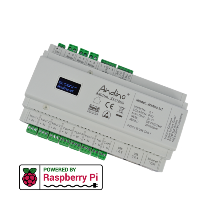
The Andino IO is an extension board for the Raspberry Pi that enables its use in an industrial environment - mounted in a DIN-rail housing for installation in a control cabinet. It is used to adapt digital inputs and outputs for a voltage of 24 V. It also contains a Raspberry Pi 3B+ or Raspberry Pi 4, depending on the configuration. The inputs and outputs as well as the power supply of the Pi are optimally protected by being re-routed to ridgid connectors.

At the heart of the IO lies a Raspberry Pi 3B+ or 4 which has enough power for even more computationally heavy tasks like webservers or databases. The Raspberry Pi is connected via its 40-pin GPIO connector. This modular design enables easy part-swapping for upgrading purposes. We also continue to build custom software, including Python libraries and Node-Red nodes. Furthermore, since our software runs on Raspberry Pi OS , you can also choose from a large library of Raspberry Pi and Debian software.
The IO board has a 9-30V wide-range DC input with reverse polarity protection. The integrated EMC protection circuits protect the Pi from voltage surges and current surges on the supply line.
The IO board has six electrically isolated inputs (up to 5kV isolated) as well as three relay outputs for 240 volts and 3 amps. The input pins can be wired up according to this diagram.
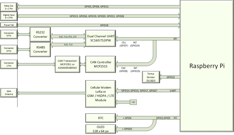
The inputs are simply connected to the Raspberry Pi GPIO. The corresponding pins are: GPIO13, GPIO16, GPIO19, GPIO20, GPIO21, GPIO26
The Andino IO has three relay outputs. They are also connected to the Raspberry Pi GPIO: GPIO5, GPIO6, GPIO12
The Andino IO has RS232 connectivity built-in (not galvanically isolated).
Important: Make sure that the ground pin (GND) has the same potential as the minus pin of the power input!
Furthermore, it has a galvanically isolated RS485/RS422 connector. This also allows the use of Modbus RTU.
CAN Bus connectivity is also possible with the Andino IO due to its integrated CAN connector.
The integrated, battery-buffered RTC provides the correct time even if no NTP (time) server is available. The high-precision time chip DS3231 from Dallas Semiconductors is used. Due to the internal temperature compensation of the oscillator, the chip achieves a very high accuracy of ± 2ppm at 0 ° C to + 40 ° C.
A 1.3 inch, 128 x 64 pixel I2C OLED display enables easy monitoring of data from the IO.
Installation instructions and usage in Node Red are here
- Production Machines
- Energy data monitoring
- Capture environmental data Interface conversions
For documentation and setup tutorials about a specific product that includes extensions, please choose an entry from this list:
- Andino IO with Raspberry Pi, LoRaWAN, Heatsink and RTC
- Andino IO with Raspberry Pi, 2G Modem, Heatsink and RTC
- Andino IO with Raspberry Pi, 4G/LTE Modem, Heatsink and RTC
The IO is also availabe without any extentions, this variant only includes the Raspberry Pi as well as the base board. For more technical documentation on the base board, including setup tutorials and download links for drivers and firmware, please refer to Andino IO: BaseBoard Setup.
If you want to read inputs and control relays via Python, please refer to our Guide using inputs and relays using the RPi.GPIO library.
- 2020 by AndinoSystems
- Contact us by email

