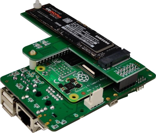
The Raspberry Pi Compute Module 4 IO Board is a secondary board that the CM4 can be mounted on. It adapts the Compute Module to the same formfactor as a Raspberry Pi and thus allows the use of traditional Raspberry Pi housing and other accessories, including all Andino boards.

All features, as well as the installation process for the CM4 IO Board can be found in the video about the topic on our Youtube Channel:
- Raspberry Pi GPIO pins
- 2x USB 2.0
- Gigabit Ethernet
- Internal USB Header
- PCI-e X1
- Micro HDMI

The PCI-e X1 pins on the IO board can be used to connect an M.2 SSD to the Raspberry Pi and therefore enabling faster read/write speeds, improved loading times, higher capacities and longevity than it would be possible when using an SD card. This is possible by using our PCI-e to M.2 adapter that is also available on our shop.

The Raspberry Pi CM4 itself also has the following features:
- Broadcom BCM2711 quad-core Cortex-A72 (ARM v8) 64-bit SoC @ 1.5GHz
- H.265 (HEVC) (up to 4Kp60 decode), H.264 (up to 1080p60 decode, 1080p30 encode)
- OpenGL ES 3.0 graphics
- 1GB - 8GB LPDDR4-3200 SDRAM (depending on variant)
- 0GB ("Lite") - 32GB eMMC Flash memory (depending on variant)
- Optional 2.4 GHz, 5.0 GHz 802.11 b/g/n/ac wireless
- Bluetooth 5.0
The exact featureset will depend on the specific version. The Compute Module 4 itself is not included when buying one of our IO boards and needs to be purchased seperately.
The Raspberry Pi Compute Module 4 has eMMC flash memory built in. On Windows and Linux, this memory can easily be flashed to by following these steps. For other platforms, please check this official Raspberry Pi documentation.
- On Windows, download and run the installer for the drivers and boot tool. On Linux, clone the usbboot git repository:
git clone https://github.com/raspberrypi/usbboot.git. Then enter the directorycd usbbootand install the program by runningmake. - Run the installed program (Windows: Run rpiboot.exe from your start menu. / Linux:
sudo ./rpiboot). - Make sure that the jumpers labeled RPI_Boot and GlobalEN on the IO Board are set. All other jumpers should not be set.
- Connect the IO board to your PC via the micro USB port.
- Power the Compute Module 4 either by providing power to the GPIO pins 2 (5V) and 6 (GND) or by plugging the IO board directly into an Andino board. (see here for a full documentation on the GPIO pins). Note: The CM4 module is not supplied with power via the USB port.
- The Compute Module eMMC should be visible as a disk after a few seconds.
- Continue by flashing Raspberry Pi OS and proceed with the installation like on a normal Raspberry Pi. For Andino boards, documentation on this is available for the Andino X1 and the Andino IO.
- When the installation is complete, eject/unmount the Compute Module from your PC, cut power to the device and then set only the GlobalEN jumper. All other jumpers should be unset. When providing power to the IO board again, it should boot normally.
By default, USB is disabled on the compute module. To enable it, edit the /boot/config.txt:
sudo nano /boot/config.txtHere, add the following line to the end of the file:
dtoverlay=dwc2,dr_mode=hostNow reboot. USB should now be enabled.
sudo nano /boot/firmware/config.txtHere, add the following line to the end of the file:
dtoverlay=dwc2,dr_mode=hostand comment this line like this:
# otg_mode=1The pinout of the IO board GPIO is equivalent to the pinout of the Raspberry Pi GPIO.
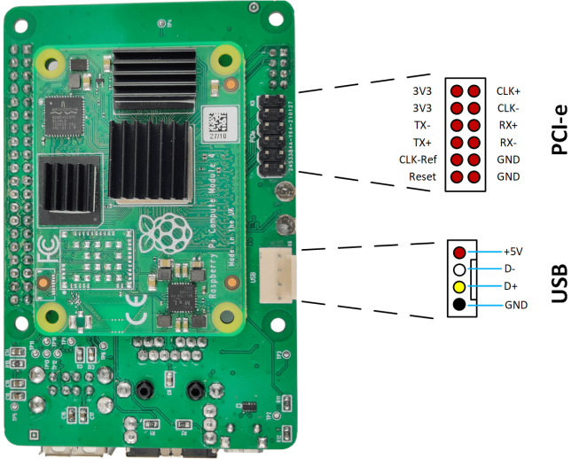
The PCIe and USB pins can be described as follows:

- 2021 by AndinoSystems
- Contact us by email


