You are welcome to use and adapt the library sources as a basis for your project.
Here is the GIT Repository
We recommend communicating directly with the firmware via the UART protocol for the Andino X1. For the "Andino IO" and "Andino Gateway", we recommend accessing the GPIO directly. Libraries for this are available for most programming languages.
This page provides details on the installation and usage of the Andino API, an event-based, simple to use library for the Andino X1, Andino IO and Andino Terminal. For a general introduction on how to communicate with inputs and outputs of your Andino board, please refer to Andinopy: Overview & Communication.
There are two ways to use the Andino API:
- By importing it into your own projects. This way, you can control the hardware of Andino board directly from your own python scripts / applications.
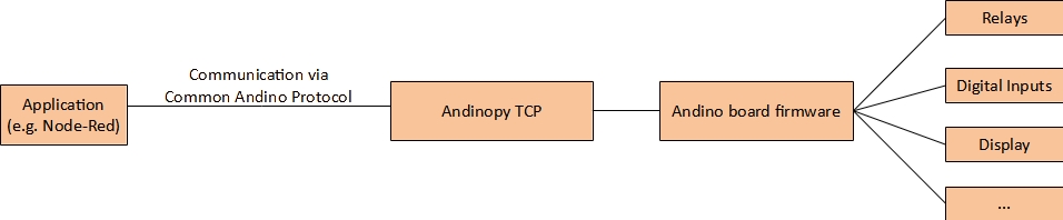
- By running its built-in TCP server to easily connect to other Andino software, to Node-Red or to your own application. The different functions can be executed by commands and the server returns status messages according to the Andino Common Protocol.
If the library hasn't already been installed as part of our install scripts, first refer to the setup section. Afterwards, depending on your desired usecase, refer to the fitting usage section. For a more detailed overview on different ways of communicating with the Andino board IO, please refer to Andinopy: Overview & Communication.
The installation of Andinopy requires Raspberry Pi to already be installed on the Raspberry Pi. Raspberry Pi OS Bullseye is supported in both 32 and 64 bit. The automatic installation does not support Raspberry Pi OS Buster, however, a manual installation with this version is still possible. If you need documentation on how to flash the firmware to an SD card, you can follow this official Raspberry Pi documentation. Make sure to create a user account and enable SSH in the advanced options of the Raspberry Pi Imager.
The easiest way to install the library, TCP stack and other significant software for Andino boards on the Raspberry Pi is by using one of our install scripts. This will install:
- Necessary overlays and software for Andino board
- Andinopy with all requirements
- NodeRed with all Andino Nodes
- Supervisor for andinopy autostart
First, download the setup script from our GitHub repository:
wget 'https://raw.githubusercontent.com/andino-systems/andinopy/main/install_scripts/setup.sh'Make the script executable:
chmod +x setup.shRun the script (example):
sudo ./setup.sh -m IO -n -s -oImportant: Change the parameters to match your hardware configuration!
Configure your board version by changing the two parameter after the -m flag. Set to:
- IO for Andino IO / Andino Terminal
- X1 for Andino X1
- XIO for Andino XIO
Other parameters:
- Set -n if you want to install NodeRed.
- Set -s if you want to install Supervisor (recommended! If you choose not to install it, you will need to set up Andinopy-TCP another way if you want to use NodeRed).
- Set -o if you want to use the OLED display functionality (Andino IO, XIO)
Set -t if you want to use a temperature sensor (Andino X1 only!)Temperature sensors are not yet available on Andinopy. If you want to use them, refer to this documentation. However, you won't be able to use Andinopy TCP in combination with the solution described there.- Set -d if your device has a Nextion Display (Andino Terminal only!)
- Set -k if your device has a RFID reader/keyboard (Andino Terminal only!)
After the installation is complete, you will find the Andino-TCP configuration file at ~/andinopy/andinopy_cfg and log files at ~/andinopy/andinopy_log. If you installed Supervisor, Andino-TCP will run automatically on startup.
Make sure to delete the install script after you have run it since executing it again will basically destroy your OS.
OLED display is displaying contents on its head
Since the configuration of the OLED display varies with the device category, it is possible for the OLED display to initially show contents in the wrong orientation. To change its configuration, there are two options:
- Via Node-Red (graphical): Log in via Node-Red, click on the "Configuration" flow and select another display rotation. Since 1 is the default display rotation, it is likely that you need to change the rotation to 0 if the image is displayed wrongly. After having send the configuration change you may need to wait up to a few minutes for Node-Red to restart. Afterwards, you can send a test message below.
- In the Andinopy config file (CLI): Log into the Andino device via SSH (default credentials are User: pi / Password: raspberry). Here, edit the file
nano ~/andinopy/andinopy_cfg/generated_saved.cfgand change the value of rotate to 0 if it was 1 before and vice-versa. Save and quit, then restart andinopy by runningsudo supervisorctl restart andinopy. The screen rotation should now have changed. If you do not see a difference, editnano ~/andinopy/andinopy_cfg/generated.cfginstead, change the same value as earlier and restart andinopy again.
First, append the following lines to the /boot/config.txt:
# SPI on
dtparam=spi=on

# I2C on
dtparam=i2c_arm=on

# RTC
dtoverlay=i2c-rtc,ds3231

# CAN on SPI 0.0
dtoverlay=mcp2515-can0,oscillator=16000000,interrupt=25

# 1. UART
enable_uart=1
dtoverlay=pi3-disable-bt-overlay
dtoverlay=pi3-miniuart-bt

# 2. SPI-UART on SPI 0.1
dtoverlay=sc16is752-spi0-ce1,int_pin=24,xtal=11059200
If you want to use DS1820 temperature sensors on the Andino X1 as well, also add the following lines:
# DS1820 Temp sensor
dtoverlay=w1-gpio-pullup,gpiopin=22,extpullup=on
dtoverlay=w1-gpio,gpiopin=22
Add the following to /etc/modules-load.d/modules.conf
i2c-devDisable console on Serial0
cut -d ' ' -f 3- < /boot/cmdline.txt | sudo tee /boot/cmdline.txtSet up Can Bus (if applicable for your board):
sudo ip link set can0 up type can bitrate 125000
sudo ifconfig can0
Set Up RTC (IO, XIO, X1)
sudo apt-get install -y i2c-tools
sudo apt-get purge -y fake-hwclock
sudo apt-get remove fake-hwclock -y
sudo dpkg --purge fake-hwclock
sudo rm -f /etc/adjtime.
sudo cp /usr/share/zoneinfo/Europe/Berlin /etc/localtime
sudo ln -s /home/pi/bin/ntp2hwclock.sh /etc/cron.hourly/ntp2hwclock
Set Up Node-Red
bash <(curl -sL https://raw.githubusercontent.com/node-red/linux-installers/master/deb/update-nodejs-and-nodered) --confirm-install --confirm-pi
sudo systemctl enable nodered.service
Set Up Andinopy
Prerequisites:
sudo apt install libopenjp2-7 libtiff5 fonts-firacode
mkdir firacode_inst
cd firacode_inst
wget https://github.com/tonsky/FiraCode/releases/download/6.2/Fira_Code_v6.2.zip
unzip Fira_Code_v6.2.zip
sudo mkdir -p /usr/share/fonts/truetype
sudo cp ttf/FiraCode-Regular.ttf  /usr/share/fonts/truetype/FIRACODE.TTF
cd ..
Installing wheel:
sudo pip3 install wheel pyserialDownload and install andinopy:
git clone https://github.com/andino-systems/andinopy.git
cd andinopy
sudo pip3 install ./dist/andinopy-0.2-py3-none-any.whl
Edit the config file at ./andinopy/default.cfg to set your board paramaters. For basic usage, it should be sufficient to change the values in the andino_tcp section to your hardware configuration. At hardware=... you can change your board configuration. Valid options are io for Andino IO / Andino XIO and x1 for Andino X1.
hardware=ioThe following individual parameters should be set to True if:
oled - Your board has an oled display
temp - You want to connect a [Temperature sensor](/andino-x1/ds18b20-sensors) to your board
key_rfid - Your hardware has an RFID-Reader (Andino Terminal)
display - Your hardware has a Nextion Display (Andino Terminal)
Start Andinopy on boot with supervisor:
sudo apt install supervisor
sudo chmod +x /etc/init.d/supervisor
sudo systemctl daemon-reload
sudo update-rc.d supervisor defaults
sudo update-rc.d supervisor enable
sudo service supervisor start
Add andinopy entry to configuration file:
sudo nano /etc/supervisor/conf.d/andinopy.confAdd the following lines:
[program:andinopy]
command=sudo python3 /usr/local/lib/python3.9/dist-packages/andinopy/__main__.py [install_dir]/andinopy/andinopy_cfg/generated.cfg
directory= [install_dir]
user=root
autostart=true
autorestart=true
startsec=3
redirect_stderr=true
stdout_logfile=[install_dir]/andinopy/andinopy_log/andinopy.stdout.txt
stdout_logfile_maxbytes=200000
stdout_logfile_backups=1
priority=900
Replace [install_dir] (at the options command, directory and stdout_logfile) with the directory that andinopy is installed in
Once installed, the power fail input of the board can also be configured to automatically shut down the board once a power outage is detected. This can be done in the configuration file:
sudo nano ~/andinopy/andinopy_cfg/generated.cfgHere, you can change the power fail pin as well as the time in seconds after which the shutdown should be initiated:
# Power-fail pin. shutdown_script will activate when pin_power_fail is active for more than shutdown_duration s.
# Python will stop
pin_power_fail=18
shutdown_duration=10
shutdown_script=bash -c "sleep 15; sudo shutdown -h now "&After the installation is finished, you can now use Andinopy as a python library inside your own projects. To use the library, import the device from the library:
import andinopy
import andinopy.base_devices.nextion_display

display = andinopy.base_devices.nextion_display.display()
display.start()

display.set_text("myObj", "myTestText") # set myObj txt to "myTestText
display.set_attr("myObj","pco", "255") # set myObj fontcolor to blueThe display provides an event handler for touch-inputs, as well as functions to set text, attributes, set pages and send raw text.
def on_display_touch( text: bytearray):
    print(f"Display Touch: {str(text)}")
    if text[:4] == b'e\x00\x17\x01':    #for more info on the bytes please refer to the nextion documentation
        print("Button was pressed")
# assign the function to the event
terminal.display_instance.on_display_touch = on_display_touch
# set the text on object txt1 to "Hello, World!"
terminal.display_instance.set_text(f"txt1", "Hello, World!")
# set the text color of object txt1 to 1346
terminal.display_instance.set_attr(f"txt1", "pco", 1346)
# set the page to "page2"
terminal.display_instance.set_page(f"page2")
For the colors, we recommend this GitHub page. The full nextion documentation with raw bytes can be found here.
RFID, Keyboard, and Buzzer are bundled in the same handler as they are received via I2C together. We provide an event for the Buttons 0 to 9, the function buttons, and RFID tags respectively. The buzzer can be toned for a specified number of milliseconds.
# Buttons 0 to 9
def on_function_button(btn: str):
    print(f"Function Button: {btn}")

# Function Buttons
def on_keyboard_button(btn: str):
    print(f"Keyboard Button: {btn}")

def on_rfid_string(rfid: str):
    # buzz for 50ms
    terminal.rfid_keyboard_instance.buzz_display(50)
    print(f"RFID: {rfid}")

# set the event handlers
terminal.rfid_keyboard_instance.on_function_button = on_function_button
terminal.rfid_keyboard_instance.on_keyboard_button = on_keyboard_button
terminal.rfid_keyboard_instance.on_rfid_string = on_rfid_stringThe Andino IO can be used on its own or as part of the Andino Terminal. You can assign a custom function to each input and there are functions to set and pulse each relay on its own. You can even set the standart config for each relay before starting the andino io.
import andinopy

andinopy.initialize_cfg("/home/pi/andinopy/andinopy_cfg/generated.cfg")
# Standard by using auto script ~/andinopy/andinopy_cfg/generated.cfg
# When you changed, must customize it!

import andinopy.base_devices.andinoio as andinoio
IO = andinoio.andinoio()
IO.on_change_functions = [lambda x=i: print(f"Input {x} changed") for i in range(len(IO.input_pins))]

IO.start()

# Set Relay on/off
IO.set_relay(1,0)
IO.set_relay(1,1)
This is only valid for the XIO/IO not for X1
When your script is stopped/interrupted, you must make sure that
IO.stop()is executed. This is giving up the Outputs free.
The Andino OLED can use two text modes for two seperate columns on the display.
You can create a new OLED with:
my_led = andino_io_oled()The OLED mode can be changed by calling
my_led. set_mode("11")or if you want two columns:
my_led. set_mode("21","30")The modes can be described as follows. When using two columns beware that only half of the chars are available.
"10":  1 Line, 3 Chars mode
"11":  1 Line, 4 Chars mode
"20":  2 Line, 6 Chars
"21":  2 Line, 9 Chars
"30":  3 Line, 9 Chars
"31":  3 Line, 12 Chars
"40":  4 Line, 14 Chars
"60":  6 Line
The text can then be set to the panel by calling set_text. Here, each array has to contain the same number of strings as the number of lines specified in the mode above. If you only use one column, you only need to pass one array. If you are using two columns with modes 21 and 30, the function call looks like this:
my_led.set_text( [["col1 row1","col1 row2"],["col2 row1","col2 row 2","col2 row3"]])Andinopy can also be used to easily communicate with applications using the Andino Protocol. Here, an application can connect to a TCP socket provided by Andinopy (port 9999 per default) and can receive messages from the devices as well as send commands to control them. For a full list of commands, please refer to the commands section of Common Andino Protocol.
For testing purposes, the server can be connected to on port 9999. If you use PuTTY, make sure to select RAW as the connection type.
If you installed Andinopy with Supervisor (if you set the -s flag when running the install script), Andino-TCP will automatically run on boot. If you want to restart the TCP stack, simply run:
sudo systemctl restart supervisor.serviceThe TCP server can be started manually by navigating to the andinopy directory and running andinopy/andino_tcp.py. If you installed the library in the pi home directory (default), you can run the server by executing:
sudo python3 ~/andinopy/andinopy/andino_tcp.pyThe server can also be started on bootup by executing the andino_tcp.py file automatically in /etc/rc.local.
To do so, first edit the file
sudo nano /etc/rc.localThe file always has to end with exit 0. Thus, insert the following before the last line:
sudo python3 /home/pi/andinopy/andinopy/andino_tcp.pyIf you installed the library in a different directory, please substitute your own file path.
The TCP server should now be started automatically on the next reboot
sudo reboot- 2022 by Andino Systems
- Contact us via Email