This page provides Technical documentation on the Andino X2 board. For a general introduction, refer to Andino-X2. For a setup tutorial on the Andino-X2 firmware, see Andino-X2: Firmware.
For all Andino X2 firmware downloads, see our GitHub repository! For scripts for the modem, visit the scripts section.
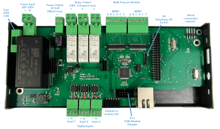
The digital inputs are connected to the Atmel Controller.
The default firmware will debounce the inputs and send changes and a change counter cyclical to the Pi.
The Inputs are calculated for 24 Volt Input.
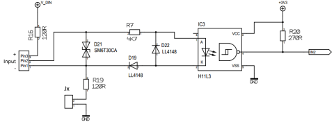
The Inputs can be driven by an external power supply (active mode) or with a "dry contact" with the internal voltage.
For the "dry contact" the internal jumper has to be closed. This will connect the "minus" contact with the ground of the board so this not a 100% isolated mode.

The Ralay are also controlled by the Atmel Controller. The default firmware can turn them on/off or pulse them.
This will be done by the command:
REL1 1
REL1 0
REL2 1
REL2 0
RPU1 1500
PRU1 1500 Pulses the relay 1 for 1500 ms.
For a detailed description of the firmware, please see here.
- Release the ttyAMA0 from getty and asign it to GIO14, GPIO15
- Add a driver for the SPI UART
- Add a driver for the SPI Ethernet controller
The UART on the GPIO is used for the 2G/GPRS Modem. First, edit the /boot/config.txt:
sudo nano /boot/config.txtMove to the bottom of the file and add this:
enable_uart=1
dtoverlay=pi3-disable-bt-overlay
dtoverlay=pi3-miniuart-bt
Save and quit.
Now, stop getty on serial0. To do this, first edit /boot/cmdline.txt:
sudo nano /boot/cmdline.txt Remove the entries starting with console=.... Entries that need to be removed in the example below are marked with >>entry<<.
dwc_otg.lpm_enable=0 >>console=serial0,115200 console=tty1<< root=/dev/mmcblk0p2 rootfstype=ext4 .....Save and exit.
The first channel goes to the MPM Slot 1. The second channnel of the SPI UART is used to communicate with the Atmel Controller.
cd ~/
wget https://github.com/andino-systems/Andino/raw/master/Andino-X2/src/sc16is752-spi0-ce1.dtbo
sudo cp sc16is752-spi0-ce1.dtbo /boot/overlays/
sudo nano /boot/config.txt
Add or uncomment this
dtparam=spi=on
dtoverlay=sc16is752-spi0-ce1
Then reboot:
sudo reboot nowCheck if the devices are showing up.
ls /dev/ttySC*ls should return two entries, namely ttySC0 for MPM1 and ttySC1 for the Arduino.
sudo nano minicom –-setupNavigate to Serial Port Setup and change the settings to the following:
+-----------------------------------------------------------------------+
| A -    Serial Device      : /dev/ttySC1                               |
| B - Lockfile Location     : /var/lock                                 |
| C -   Callin Program      :                                           |
| D -  Callout Program      :                                           |
| E -    Bps/Par/Bits       : 38400 8N1                                 |
| F - Hardware Flow Control : No                                        |
| G - Software Flow Control : No                                        |
|                                                                       |
|    Change which setting?                                              |
+-----------------------------------------------------------------------+
        | Screen and keyboard      |
        | Save setup as dfl        |
        | Save setup as..          |
        | Exit                     |
        | Exit from Minicom        |
        +--------------------------+
You can exit minicom by pressing Ctrl+A, followed by x.
To add the driver, first edit the /boot/config.txt:
sudo nano /boot/config.txtNavigate to the end of the file and add
dtoverlay=enc28j60Now reboot.
sudo reboot nowAfter the reboot is complete, run ifconfig and check if the interface shows up correctly:
ifconfig
eth0: flags=4163<UP,BROADCAST,RUNNING,MULTICAST>  mtu 1500
inet 192.168.178.74  netmask 255.255.255.0  broadcast 192.168.178.255
inet6 fe80::50a1:6c17:239b:847c  prefixlen 64  scopeid 0x20<link>
ether b8:27:eb:45:a3:bc  txqueuelen 1000  (Ethernet)
RX packets 2077  bytes 186482 (182.1 KiB)
RX errors 0  dropped 3  overruns 0  frame 0
TX packets 1649  bytes 257186 (251.1 KiB)
TX errors 0  dropped 0 overruns 0  carrier 0  collisions 0

eth1: flags=4099<UP,BROADCAST,MULTICAST>  mtu 1500
ether c6:97:8d:3a:22:b6  txqueuelen 1000  (Ethernet)
RX packets 0  bytes 0 (0.0 B)
RX errors 0  dropped 0  overruns 0  frame 0
TX packets 0  bytes 0 (0.0 B)
TX errors 0  dropped 0 overruns 0  carrier 0  collisions 0
device interrupt 191Enable I2C and add the Module the RTC DS3231
sudo nano /boot/config.txtuncomment dtparam=i2c_arm=on and add the dtoverlay=i2c-rtc,ds3231
dtparam=i2c_arm=on
#dtparam=i2s=on
#dtparam=spi=on
dtoverlay=i2c-rtc,ds3231
Execute this
sudo -s
chmod +x /etc/rc.local
apt-get install -y i2c-tools
apt-get purge -y fake-hwclock
apt-get remove fake-hwclock -y
dpkg --purge fake-hwclock
rm -f /etc/adjtime.
cp /usr/share/zoneinfo/Europe/Berlin /etc/localtime
ln -s /home/pi/bin/ntp2hwclock.sh /etc/cron.hourly/ntp2hwclock
sudo reboot now
After reboot test this RTC
pi@raspberrypi:~ $ i2cdetect -y 1

     0  1  2  3  4  5  6  7  8  9  a  b  c  d  e  f
00:          -- -- -- -- -- -- -- -- -- -- -- -- --
10: -- -- -- -- -- -- -- -- -- -- -- -- -- -- -- --
20: -- -- -- -- -- -- -- -- -- -- -- -- -- -- -- --
30: -- -- -- -- -- -- -- -- -- -- -- -- -- -- -- --
40: -- -- -- -- -- -- -- -- -- -- -- -- -- -- -- --
50: -- -- -- -- -- -- -- -- -- -- -- -- -- -- -- --
60: -- -- -- -- -- -- -- -- 68 -- -- -- -- -- -- --
70: -- -- -- -- -- -- -- --
pi@raspberrypi:~ $

hwchwclock -w
hwclock -r
This Python script sets the NTP Time to the HWClock as long a NTP connection can established. Place this script at /home/pi/bin/ntp2hwclock.sh (for example, see above)
#!/bin/bash
# Location of logfile
LOGFILE="/usr/local/oeebox/etc/log/ntp.log"
if [ ! -f $LOGFILE ]; then
  touch $LOGFILE
fi
# Set the maximum allowed difference in seconds between Hw-Clock and Sys-Clock
maxDiffSec="2"
msgNoConnection="No connection to time-server"
msgConnection="Connection to time-server"
# Check for NTP connection
if ( ntpq -p | grep -q "^*"  ); then
        echo $msgConnection >> $LOGFILE
        echo "---------------------------------"  >> $LOGFILE
        secHwClock=$(sudo hwclock --debug | grep "^Hw clock time" | awk '{print $(NF-3)}')
        echo "HwClock: $secHwClock sec" >> $LOGFILE
        secSysClock=$(date +"%s")
        echo "SysClock: $secSysClock sec" >> $LOGFILE
        echo "---------------------------------" >> $LOGFILE
        secDiff=$(($secHwClock-$secSysClock))
        # Compute absolute value
        if ( echo $secDiff | grep -q "-" ); then
            secDiff=$(echo $secDiff | cut -d "-" -f 2)
        fi
        echo "Difference: $secDiff sec" >> $LOGFILE
        msgDiff="HwClock difference: $secDiff sec"
        if [ "$secDiff" -gt "$maxDiffSec" ] ; then
                echo "---------------------------------" >> $LOGFILE
                echo "The difference between Hw- and Sys-Clock is more than $maxDiffSec sec." >> $LOGFILE
                echo "Hw-Clock will be updated" >> $LOGFILE
                # Update hwclock from system clock
                sudo hwclock -w
                msgDiff="$msgDiff --> HW-Clock updated." >> $LOGFILE
        fi
        if !(awk '/./{line=$0} END{print line}' $LOGFILE | grep -q "$msgConnection") || [ "$secDiff" -gt "$maxDiffSec" ]; then
                echo $(date)": "$msgConnection". "$msgDiff >> $LOGFILE
        fi
else
        # No NTP connection
        echo $msgNoConnection
        if !(awk '/./{line=$0} END{print line}' $LOGFILE | grep -q "$msgNoConnection"); then
                echo $(date)": $msgNoConnection" >> $LOGFILE
        fi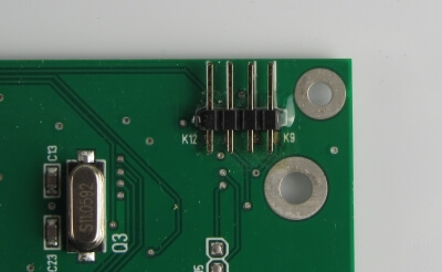
fiThe UART communication with the Atmel Controller can be switched to either the Raspberry Pi or an external PC with a USB Adapter. With this the firmware development can be easily done with a PC.
The selection is done by two jumpers.

If the Jumpers are pluged in the communication takes place between the Pi and the Atmel.
If the Jumpers are not pluged in, the communication takes place between the Atmel and the PC.

The device to communicate with the Atmel is /dev/ttySC1
The Baudrate with the default firmware is 38400 Baud with 8/n/1 and no hardware flow control.
You can easily check this with minicom.
sudo apt-get install minicom
sudo minicom --setup
Use ctrl-a and then x to exit minicom.
The Andino X2 allows to program the Atmel Controller from the Raspberry Pi via avrdude or using a PC and a USB Adapter.
This Adapter is available on our shop or Ebay.

The Jumper at the Atmel connection Selector must not be plugged in.
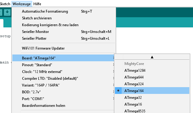
To program the Atmel Controller with the Arduino IDE just install Mighty Core Boards.
Please visit their GitHub repository and refer to the "How to install" section.
Use these settings inside the Arduino IDE:
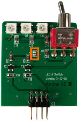
The six LED in the Lid are RGB WS2812. There are driven by the GPIO 18.
Please note: Drive the LED with a maximum brightness of 50% (Value 128)!
You can drive the left three LED from the Raspberry and the three left from the Atmel.
If you short cut the Jumper J1 you will be able to controll all six LED from the Raspberry.
How to install the software:
First, update the package lists and install a few new packages
sudo apt-get update
sudo apt-get install gcc make build-essential python-dev git scons swig
Download jgarff from github
git clone https://github.com/jgarff/Afterwards, run
rpi_ws281x
cd rpi_ws281x/
sudo scons
cd python
Now run the setup scripts
sudo python setup.py build
sudo python setup.py install
Finally, set the configuration in the example file
cd examples
nano lowlevel.py
change the LED COUNT and the LED GPIO and the Brightness:
# LED configuration.
LED_CHANNEL = 0
LED_COUNT   = 3      # How many LEDs to light.
LED_FREQ_HZ = 800000 # Frequency of the LED signal.  Should be 800khz or 400khz.
LED_DMA_NUM = 5      # DMA channel to use, can be 0-14.
LED_GPIO    = 18     # GPIO connected to the LED signal line.  Must support PWM!
LED_BRIGHTNESS = 128 # Set to 0 for darkest and 255 for brightest
LED_INVERT = 0  # Set to 1 to invert the LED signal, good if using NPN
You can now test the configuration:
sudo python lowlevel.pyYou can find an example of how to drive the LED from the Atmel as well as the firmware for the controller in the firmware section
For an installation tutorial as well as documentation, please refer to SimCom SIM800L: Setup (2G/EDGE Modem).
Physical GSM connector: