This page provides documentation on the Andino X2 firmware. For a general introduction, refer to Andino-X2. For more technical documentation on the base board, including setup tutorials and download links for drivers, please refer to Andino X2: Technical Documentation.
To develop a new firmware for the Andino X2 from a PC, please follow this steps:
- Download the Arduino IDE here
- Read the "How to install the Board Defintion" here
- Setup the Arduino IDE
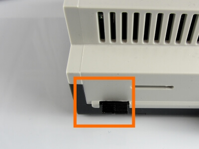
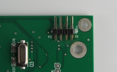
- Pull the Jumper
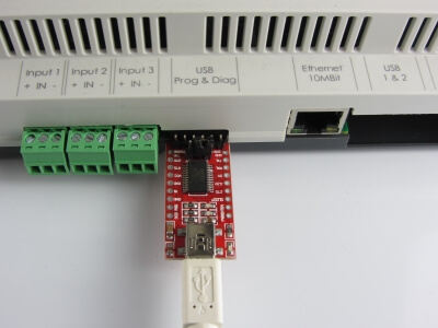
- Plug in the USB Convert and select the COM-Port
The Andino X2 allows to program the Atmel Controller from the Raspberry Pi with avrdude or from a PC via a USB Adapter.
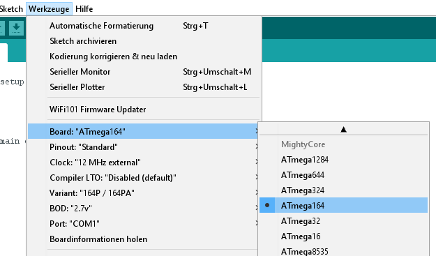
To program the Atmel Controller with the Arduino IDE just install the Mighty Core Boards.
Please visit this site https://github.com/MCUdude/MightyCore and see "How to install"
Use this settings inside the Arduino IDE:
Here you will find the initial Firmware: firmware.ino installed on the X2.
To use the Controller with the Arduino IDE the jumper must not be pluged in.
This Adapter is available at our shop or from ebay. Leave the Jumper to 5 Volt.
The Andino X2 uses the Atmega164PA with 12Mhz clock.

#define PIN_WIRE        31  // PA7: Dallas temperatur sensor
#define LED_PIN         18  // PC2: NeoPixel bus

#define IN_1_PIN        27  // PA3: digital Input 1
#define IN_2_PIN        28  // PA4: digital Input 1
#define IN_3_PIN        29  // PA5: digital Input 1
#define SWITCH_PIN      30  // PA6: digital Input 1

#define POWER_OUT_PIN   3   // PB3: & Power Out
#define RELAY_1_PIN     0   // PB0: Rel 1
#define RELAY_2_PIN     1   // PB1: Rel 2
#define RELAY_3_PIN     2   // PB2: Rel 3
The default firmware, witch is inital delivered uses 38400 Baud to communicate to ether the PC or the Raspberry (the jumpers)
This is what the Firmware do:
- Scan the digital Inputs and debounce it
- Count the (debounced) L-H or H-L Edges on the digital Inputs
- Switch the Relay on/off or pulse it
- Controlls the RGB LED
- Read the temperature sensor
- Send the Input State and Counter cyclical
All commands or messages are sent and received via /dev/ttySC1
All character are ASCII.
Every command has to be terminated by CR or LF. Message ends with CR and LF.
You can easily test the commands with minicom
sudo minicom --setupSet the device to /dev/ttySC1, 38400 Baud, no Hardware Handshake.
| Command | Arguments | Action | Example |
|---|---|---|---|
| RESET | none | Restart the Controller | RESET |
| INFO | none | Prints the current settings | INFO |
| HARD | 0=noShield, 1=1DI2DO, 2=3DI | Set the Hardware configuration | 0 - none |
| POLL | Cycle in ms | Sets the sampling cycle of the digital inputs [in ms] | POLL 1000 |
| EDGE | HL(0) LH(1) | Count on edge HL or LH | EDGE |
| SEND | Cycle in ms | The counter will send all nnn milliseconds | SEND 5000 |
| DEBO | Number of polls | Sets the debounce count. The signal has to be stable for nn polls | DEBO 100 |
| POWR | state (0 or 1) | Power-Out Relay is switched on or off | POWR 1 |
| REL1 | state (0 or 1) | Relay 1 is switched on or off | REL1 1 |
| REL2 | state (0 or 1) | Relay 2 is switched on or off | REL2 1 |
| REL3 | state (0 or 1) | Relay 3 is switched on or off | REL2 1 |
| RPU1 | pulse in sec | Pulse the Relay 1 for nn seconds | RPU1 2 |
| RPU2 | pulse in sec | Pulse the Relay 2 for nn seconds | RPU2 2 |
| RPU3 | pulse in sec | Pulse the Relay 3 for nn seconds | RPU3 2 |
| PPWR | pulse in sec | Pulse the Power-Out Relay for nn seconds | PPWR 2 |
| TEMP | none | Request the Temperature | TEMP |
| LED1 | RGB | Set the LED1 R=0..9, G=0..9, B=0..9 | LED1 900 (=max Red) |
| LED2 | RGB | Set the LED2 R=0..9, G=0..9, B=0..9 | LED3 90 (=max Green) |
| LED3 | RGB | Set the LED3 R=0..9, G=0..9, B=0..9 | LED4 9 (=max Blue) |
:Message-ID{0000,counter1,counter2,..}{switch-state,state1,state2,..}
The Message starts with a ':'.
After that follows a Message-ID. This is a modulo HEX Counter from 0..FFFF.
Then within a '{' '}' the counter follows.
The first counter is 0. This is the switch in the lid.
The number of the following counters depends on the extension shields.
The Counters are HEX encoded and runs from 0 to FFFF (modulo).
Then again within a '{' '}' the current state of the inputs follows. 0-off, 1-on.
The first state is the switch in the lid.
The number depends on the Hardware.
The Message ends with a CR / LF [0x0d + 0x0a]
Example
:0040{0000,0002,0000,000B}{0,0,0,0}
:0041{0000,0002,0000,000B}{0,0,0,0}
:0042{0000,0004,0000,000C}{0,0,0,0}
:0043{0000,0004,0000,000C}{0,0,0,0}
:0044{0000,0008,0000,000F}{0,0,1,0}
:0045{0000,0008,0000,000F}{0,0,1,0}
:0046{0000,000A,0000,0000}{0,0,1,0}
:0047{0000,000C,0000,0000}{1,0,0,0}
:0048{0000,0010,0000,0000}{0,0,0,0}
sudo apt-get install python-serialCreate test.py and run with python test.py
import serial
import time

port = serial.Serial("/dev/ttySC1", baudrate=38400, timeout=0.5)

port.write("LED1 900\r")
port.write("REL1 1\r")
time.sleep(1)
port.write("REL1 0\r")
port.write("LED1 0\r")

while True:
     rcv = port.read(50)
     if not rcv:
        continue
print "\r\nRecv: " + repr(rcv)- 2020 by AndinoSystems
- Contact us by email