This page provides a general introduction about the Andino UPS. For more technical documentation and details about the mode of operation of the firmware, refer to Andino-UPS (Uninterruptible Power Supply) Firmware

Andino UPS is an Uninterruptible Power Supply for 24 Volt DC Client Devices. It stores the Energy in long lasting Supercaps instead of Lead- or Lithium Batteries. Depending on the environment temperature, the lifetime can reach up to 10 years without any maintenance.

This UPS is designed for industrial PLC and other devices powered with 24 V DC. It is intended to allow the client device to bridge over short voltage drops and, in the event of a prolonged power failure, to shut down in a controlled manner, allowing the controlled device to close databases, connections and synchronize the file system without the risk of data loss.
The Andino UPS has a 24V DC Input and a 24V DC Output. This reduces the energy loss for the conversion to mains power and backwards.
The UPS can deliver up to 10 Watts or 0,4 Ampere at 24 Volts.
Depending on the device you want to connect, the UPS power fail input needs to be wired differently. Make sure to choose the correct configuration for your device. Wrong wiring may cause irreversible damage to the device.
If the UPS is used with the Andino X1, it should be wired as follows:
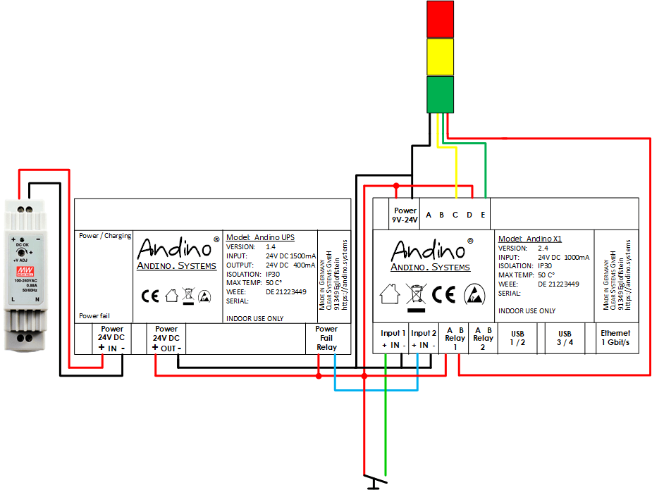
To connect the UPS with the Andino IO, you need to connect the Power Fail Input of the IO with the Power Fail Relay on the UPS. The 24V DC Out of the UPS can then be connected with the DC Power input of the IO. The 24V Power Input of the UPS needs to be connected to a DC Power Supply.

The IO will receive a shutdown signal from the UPS via the Power Fail Input when the battery capacity of the UPS reaches 80%. For the IO to initiate a shutdown, some configuration needs to be made:
Connect to the Raspberry Pi via SSH, then edit the /boot/config.txt:
sudo nano /boot/config.txtHere, add the following line to the end of the file:
dtoverlay=gpio-shutdown,gpio_pin=18,active_low=0Then, reboot the Pi by running sudo reboot now. Automatic shutdown is now configured.
The UPS can be used to power any 24 Volt Client device. To do so, the device has to be wired as follows:

Depending on the Load the backup times are:
2 Watts: 3 min 30 sec
4 Watts: 1 min 12 sec
10 Watts: 39 sec

If the charge level is above the Good Level (which - per default - is set to 80%, but is also configurable), the client will not be informed about the power fail. If the power returns within this time, the gap is bridged. This allows for the seemless continuation of operations during short outages lasting only a few seconds.

If the power returns after the client is informed, the UPS will wait until the charge level is above the Good Level again and give the client time to shut down (HYST-Timer). After that, the power to the client will be cut down (DOWN Timer) and switched on again, thus triggering a client restart.

The Andino UPS has been extensively tested for its electromagnetic compatibility (EMC).
The tests were based on the immunity to electrostatic discharge, high-frequency electromagnetic fields, fast transient electrical disturbances (burst), impulse voltages, conducted disturbances – induced by high-frequency fields and magnetic fields with energy-related frequencies.
The tested standards in detail
Radiated field strength / conducted emissions
DIN EN 55022: 2011 according to VDE 0875 part 22 of 12.2011
Störaussendung: Klasse B (Wohnbereich) (strengere Grenzwerte)
Störfestigkeit: Klasse A (Industriebereich) herangezogen. (höhere Einstrahlung)

Immunity ESD
DIN EN 61000-4-2: 2009 according to VDE 0847 part 4-2 of 12.2009

Immunity radiated electromagnetic fields
DIN EN 61000-4-3: 2006+A1:2008+ A2: 2010 according to VDE 0847 part 4-3 of 04.2011

Immunity Burst
DIN EN 61000-4-4: 2012 according to VDE 0847 part 4-4 of 04.2013

Immunity Surge
DIN EN 61000-4-5: 1995 +A1: 2014 according to VDE 0847 part 4-5 of 03.2015

Immunity high frequent uncoupled emission
DIN EN 61000-4-6: 2014 according to VDE 0847 part 4-6 of 08.2014

Immunity magnetic fields
DIN EN 61000-4-8: 2010 according to VDE 0847 part 4-8 of 11.2010
The full EMC certificates and all other reports for the Andino UPS can be viewed here.

For a description of the internal charge and power controller see here