Andino IO / Raspberry Pi: OLED display control nodes (Adafruit SSD1306)
Package name: node-red-contrib-andinooled
A Node Red node that enables processing of text for the AndinoIO OLED display (Adafruit SSD1306). This page explains the process of using the Node-Red with the OLED display of the Andino IO. For an installation guide on the display driver and custom python script, which is required for using Node-Red with the display, please refer to Andino IO: Using the OLED display
Important: Due to the migration to the new Adafruit library, the OLED Node-Red connection is temporarily unavailable. This will be fixed with the upcoming unified Andino libraries & firmware in June/early July 2021. Displaying messages using python scripts as described in this tutorial, however, still works normally.
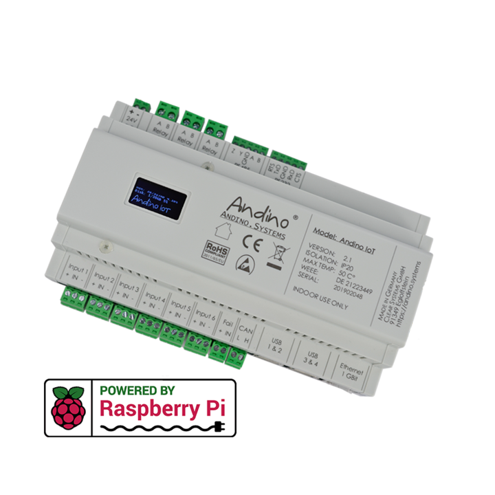
Andino boards, like the Andino IO, Andino X2 and Andino X1 enable the usage of the Raspberry Pi in industrial environments by providing a housing, several digital inputs and relay outputs.
For more information, please refer to:
Node documentation
Requirements / Prerequisites
This node allows for easy control of the OLED display of Andino IO boards via Node-Red. The node needs Adafruit Python SSD1306 as well as the custom Python script for Andino IO displays to be installed. For a detailed installation guide, see here.
Usage
TCP node configuration
The communication between the Node-Red component and the python script takes place via TCP. To establish a connection, start the TCP server as described in the installation tutorial, then drag a tcp out node to the main screen of Node-Red and connect it to the output side of the AndinoOLED node. Double click the TCP node and set the properties to: Connect to, port 2961 and enter the hostname localhost. Click Done to finish the node configuration.
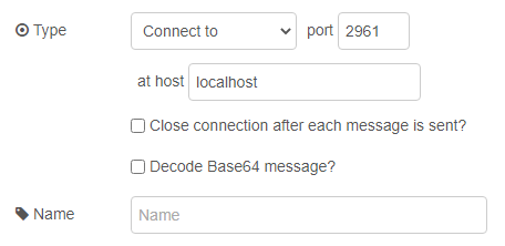
Note: By default, the TCP server only listens on localhost, this can be changed by editing the python script (look for HOST = 'localhost' at the very bottom of the script if needed.
AndinoOLED node configuration
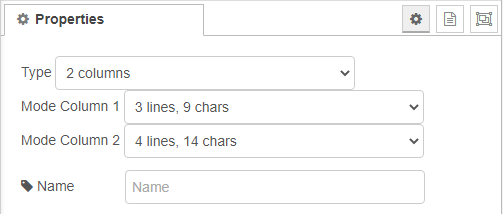
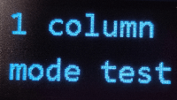
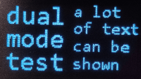
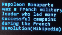
Double click the AndinoOLED node to start the configuration. Here, the output mode can be selected. Firstly, choose how many columns (one or two) the output text should have.
Afterwards, select the mode for both columns. The modes can be differentiated by the amount of lines and number of characters that fit on the screen. Chars always refers to the number of characters that fit on the screen when 1 column is selected as the type, if 2 columns is selected, only half of the listed number of characters will fit into the column.
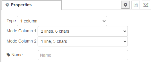
Note: When selecting 1 column as the type, all configuration and inputs for column 2 will be ignored.
Depending on the configuration, these are some possible output formats:
AndinoOLED node input
The AndinoOLED node is triggered every time it receives an input. It expects two arrays with 6 Strings for both columns, these must be named msg.lines1 for column 1 and msg.lines2 respectively. Every object in the array will be printed as a new line on the display, if a mode with less than 6 lines is chosen in the node properties, the extra Strings will be disregarded.
As a simple way to test the node, the arrays can be created using a function node. Double click the function node and enter the following code under the function tab:
var lines1 = ["test1", "test2", "test3", "test4", "test5", "test6"]
var lines2 = ["test7", "test8", "test9", "test10", "test11", "test12"]
msg.lines1 = lines1;
msg.lines2 = lines2;
return msg;
Click Done and connect the function node to the AndinoOLED node and an inject node:
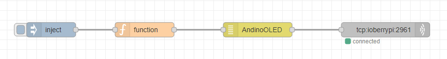
When clicking the button on the inject node, the array messages should now appear on the display.
Sample flows
For sample flow downloads, refer to our GitHub repository!